The Permanent Magnet Moving Coil (PMMC) Meter is widely used in electrical measurement systems where accurate DC readings are required. Its high sensitivity, reliable performance, and nearly uniform scale make it an important instrument in electrical laboratories, testing equipment, and DC measurement applications. Understanding its construction and operating characteristics helps explain why it is preferred for precision measurements.
What Is a Permanent Magnet Moving Coil (PMMC) Meter?
A Permanent Magnet Moving Coil (PMMC) meter is a precision electrical measuring instrument that uses the interaction between a permanent magnetic field and a current-carrying coil to measure direct current (DC). It is also known as a D’Arsonval movement and forms the basic measuring mechanism of many DC ammeters and voltmeters.
The instrument consists of a lightweight rectangular coil mounted on a spindle and placed between the poles of a permanent magnet. When DC passes through the coil, the magnetic field exerts forces on its conductors, creating a turning effect known as deflecting torque. This causes the coil and its attached pointer to rotate over a calibrated scale.
The magnetic system is designed with shaped pole pieces and a soft-iron core to produce a nearly radial magnetic field. This arrangement maintains an effective magnetic interaction as the coil rotates. The direction of force on the current-carrying conductors can be determined using Fleming’s left-hand rule.
As the coil moves, spiral control springs develop an opposing torque. The pointer stops when the deflecting torque becomes equal to the controlling torque. Since the deflecting torque is proportional to coil current and the controlling torque is proportional to angular displacement, the pointer deflection is directly proportional to the measured current. This produces a nearly uniform scale.
Why Can’t a Conventional PMMC Meter Measure AC Directly?
A conventional PMMC movement is designed for DC measurement. When AC is applied, the current reverses direction during every half-cycle, causing the deflecting torque to reverse as well. At normal operating frequencies, the mechanical inertia of the moving system prevents the pointer from following these rapid changes. The average torque over a complete cycle is approximately zero, so the instrument cannot provide a steady AC reading.
However, a rectifier circuit can be combined with a PMMC movement to measure AC. Such instruments are generally calibrated to display the RMS value of a sinusoidal waveform, although the movement itself responds to the average value of the rectified current.
Construction of a PMMC Meter
A PMMC instrument is designed to produce accurate and sensitive measurements with minimum power consumption. Its construction includes a magnetic system, moving coil, control mechanism, damping arrangement, and indicating system.
The construction digaram of Permanent Magnet Moving Coil (PMMC) Meter is shown in the image below.
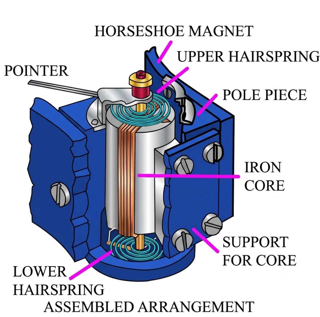
The main components of a PMMC meter are described below.
1. Permanent Magnet System
The permanent magnet produces the magnetic field required for the operation of the instrument. It is generally made from a high-quality magnetic material capable of maintaining stable magnetic strength over a long period.
Shaped pole pieces and a cylindrical soft-iron core are used to create a strong, nearly radial magnetic field in the air gap. This arrangement helps maintain a consistent deflecting torque as the coil rotates.
Alnico and other suitable permanent magnet materials may be used depending on the instrument design.
2. Moving Coil
The moving coil is the main current-carrying component of a PMMC instrument. It consists of several turns of fine insulated copper wire wound around a lightweight rectangular former, commonly made of aluminium.
The coil is placed in the narrow air gap between the permanent magnet poles and mounted on a spindle. A pointer is attached to the spindle so that it moves across the graduated scale when the coil rotates.
The aluminium former also helps provide electromagnetic damping during pointer movement.
3. Controlling System
The controlling system provides the restoring torque required to balance the deflecting torque. In conventional PMMC instruments, two spiral control springs are connected to the moving coil.
These springs perform two important functions:
- They produce controlling torque that opposes the rotation of the coil.
- They provide electrical connections to carry current into and out of the moving coil.
As the coil rotates, the springs develop an opposing torque. The pointer stops when the deflecting torque becomes equal to the controlling torque.
4. Damping System
The damping system reduces unwanted oscillations of the pointer and helps it settle quickly at the correct reading.
In a typical PMMC instrument, the aluminium former moves through the magnetic field and develops eddy currents. These currents produce an opposing electromagnetic torque that slows down the motion of the coil.
This process is called eddy current damping. It provides effective damping without significantly affecting the final steady-state reading.
5. Pointer and Calibrated Scale
A lightweight pointer is connected to the moving coil through a spindle. When the coil rotates, the pointer moves over a calibrated scale to indicate the measured current or voltage.
The scale of a conventional PMMC instrument is nearly uniform because pointer deflection is directly proportional to the current flowing through the coil.
Working Principle of PMMC Meter
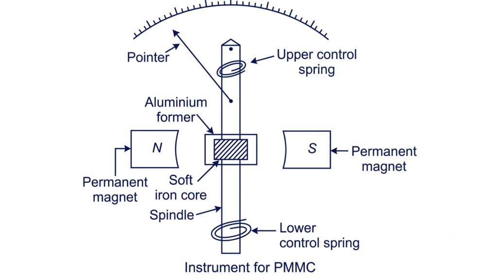
A PMMC meter works on the principle that a current-carrying coil placed in a magnetic field experiences a mechanical torque. The resulting torque causes the coil to rotate, producing pointer deflection.
When DC flows through the moving coil, a magnetic field is produced around its conductors. This field interacts with the magnetic field of the permanent magnet and generates a deflecting torque.
The moving coil rotates along with the attached pointer. As the coil moves, the control springs produce an opposing torque. The rotation continues until both torques become equal.
At this position, the pointer settles on the scale and indicates the value of the measured current.
The deflecting torque depends on the magnetic flux density, number of coil turns, coil area, and current flowing through the coil. Since the magnetic field and coil dimensions remain constant, the deflection is proportional to the current.
PMMC Meter Torque Equation
The deflecting torque produced in a PMMC instrument is given by:
Where:
- = Deflecting torque in N·m
- = Number of turns in the moving coil
- = Magnetic flux density in the air gap (tesla)
- = Current flowing through the moving coil (ampere)
- = Area of the moving coil (m²)
For a given instrument, the number of turns, magnetic flux density, and coil area are constant. Therefore:
Here, (G=N B A) is the torque constant of the instrument.
The controlling torque produced by the spiral springs is:
Where:
- = Controlling torque
- = Spring constant
- = Angular deflection of the pointer
At the steady position, the deflecting torque equals the controlling torque:
Therefore:
Rearranging:
This equation shows that pointer deflection is directly proportional to the current flowing through the moving coil. Consequently, a PMMC instrument has a nearly linear or uniform scale.
Range Extension of a PMMC Meter
A PMMC movement is generally designed to carry only a small current. To measure higher currents or voltages, additional resistors are connected to the instrument.
The measuring range can be extended in two main ways:
1. Using a Shunt Resistor in a PMMC Ammeter
A PMMC movement is designed to carry only a limited amount of current. To measure higher current values, a low-resistance shunt is connected in parallel with the moving coil. This arrangement allows the instrument to function as an ammeter with an extended measuring range.
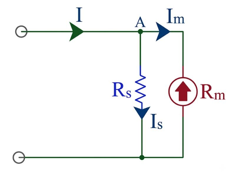
When the total current enters the parallel combination, it divides into two branches. A small portion, , flows through the moving coil, while the remaining current, , passes through the shunt resistor. Since both branches are connected in parallel, the voltage across them is equal.
The total current can be expressed as:
According to Ohm’s law, the voltage across both parallel branches is:
Therefore, the shunt resistance is:
Since , the equation becomes:
Where:
- = Resistance of the shunt
- = Resistance of the moving coil
- = Full-scale current of the moving coil
- = Current flowing through the shunt
- = Desired full-scale current of the ammeter
Shunt Multiplying Factor
The current range of a PMMC ammeter can also be expressed using the shunt multiplying factor. It represents the ratio of the desired ammeter range to the full-scale current of the moving coil.
Substituting this relationship into the shunt resistance equation gives:
Here, is the multiplying factor of the shunt.
Selection of Shunt Material: The shunt must maintain a stable resistance under varying operating temperatures and load conditions. Manganin is commonly used in precision shunts because it has a low temperature coefficient of resistance. Its current-carrying capacity and power rating must also be adequate to prevent overheating and measurement errors.
2. Using a Series Resistor in a PMMC Voltmeter
A PMMC movement can also be used as a DC voltmeter by connecting a high-value resistance in series with the moving coil. This resistance is known as a multiplier resistor.
The multiplier limits the current flowing through the coil when the instrument is connected across a voltage source.
The required series resistance is:
Where:
- = Series multiplier resistance
- = Desired full-scale voltage
- = Full-scale current of the moving coil
- = Moving-coil resistance
By selecting an appropriate multiplier resistance, the same PMMC movement can measure different DC voltage ranges.
Errors in PMMC Instruments
Although PMMC instruments provide good accuracy, certain operating conditions can affect their readings. The major sources of error include:
1. Temperature Variations
The resistance of the copper moving coil increases with a rise in temperature because copper has a positive temperature coefficient of resistance of approximately 0.0039 per °C near room temperature. As the coil heats up, its resistance increases, which can affect the current flowing through the movement and introduce measurement errors.
Temperature variations can also influence the magnetic strength of the permanent magnet and the stiffness of the control springs. These changes may affect the deflecting and controlling torques, resulting in variations in pointer indication.
The effects of temperature can be reduced by using suitable compensation techniques, stable magnetic materials, and properly rated shunt and multiplier resistors. Avoiding excessive coil heating and maintaining the instrument within its specified operating temperature range also help improve measurement accuracy.
2. Ageing of Permanent Magnets
The magnetic strength of a permanent magnet may change gradually due to ageing, prolonged exposure to high temperatures, or other environmental influences. These changes can alter the magnetic flux density in the air gap and affect the torque sensitivity of the PMMC movement.
Since the deflecting torque depends directly on magnetic flux density, any reduction in field strength can change the pointer deflection for a given current, resulting in measurement errors.
To minimise this effect, manufacturers use stable permanent magnet materials and suitable magnetic stabilisation processes. The assembled instrument is also calibrated under specified operating conditions to maintain reliable measurement accuracy.
3. Ageing of Control Springs
The control springs provide the restoring torque required to bring the PMMC pointer to its correct position. Over time, ageing, mechanical fatigue, and temperature variations can change the stiffness and characteristics of these springs.
A change in spring stiffness affects the restoring torque and alters the relationship between coil current and pointer deflection. The spring condition can also influence the instrument’s zero position. In addition, changes in electrical contact resistance may introduce further measurement errors.
These effects can influence the accuracy of the PMMC meter. Therefore, the spring characteristics, zero position, and electrical contacts should remain within specified calibration limits. Regular inspection and recalibration help maintain reliable readings.
4. Mechanical Friction
Friction in the moving system, particularly at the bearings or suspension, can prevent the pointer from moving freely. It may cause errors, especially when measuring very small currents.
Proper bearing design, careful maintenance, and a lightweight moving assembly help minimise this problem.
5. External Magnetic Fields
External magnetic fields may interfere with the magnetic field produced by the permanent magnet. This can affect the deflecting torque and lead to inaccurate readings.
A suitable magnetic shield can be provided to reduce the influence of external magnetic fields.
Advantages of PMMC Instruments
The major advantages of Permanent Magnet Moving Coil instruments are:
- High accuracy: PMMC instruments provide accurate measurements of DC current and voltage.
- Uniform scale: Pointer deflection is directly proportional to the measured current, resulting in a nearly linear scale.
- High sensitivity: A small current can produce a noticeable pointer movement.
- Low power consumption: The instrument requires relatively little electrical power for operation.
- Effective damping: Eddy current damping allows the pointer to settle quickly without excessive oscillations.
- Good repeatability: A stable magnetic system and moving mechanism provide consistent readings under specified operating conditions.
- Multiple applications: The same basic movement can be used as a DC ammeter, DC voltmeter, or galvanometer with suitable circuit arrangements.
Disadvantages of PMMC Instruments
Despite their accuracy, PMMC instruments have certain limitations:
- DC measurement only: A conventional PMMC movement cannot directly measure AC because the torque reverses during each half-cycle.
- Higher cost: Precision components and a permanent magnet assembly can make these instruments more expensive than some moving-iron instruments.
- Temperature sensitivity: Changes in coil resistance, spring characteristics, and magnetic flux can affect accuracy.
- Mechanical sensitivity: The moving coil, pointer, and bearing arrangement require careful handling.
- Overload limitations: Excessive current can damage the fine moving-coil winding unless suitable protection is provided.
Applications of PMMC Instruments
PMMC instruments are widely used in electrical and electronic measurement applications where accurate DC readings are required.
Common applications include:
- DC ammeters: Used to measure direct current in electrical circuits, battery systems, and DC power supplies.
- DC voltmeters: Used to measure DC voltage with the help of a suitable series multiplier resistor.
- Galvanometers: Used to detect and measure small electrical currents.
- Battery testing: Used in suitable DC measuring arrangements for monitoring battery voltage and current.
- Electronic testing equipment: Used in laboratory instruments, testing panels, and electronic measuring devices.
- Control panels: Used for indicating DC current and voltage in industrial electrical systems.
Conclusion
A Permanent Magnet Moving Coil (PMMC) meter is a sensitive and accurate instrument used for measuring DC current and voltage. Its operation is based on the interaction between the magnetic field of a permanent magnet and the current flowing through a moving coil.
The radial magnetic field, spring-controlled movement, and eddy current damping provide a nearly uniform scale and stable pointer indication. Although a conventional PMMC movement cannot directly measure AC, its range can be extended using shunt and multiplier resistors, and rectifier circuits can be added for AC measurement. These characteristics make PMMC instruments useful in laboratories, electrical testing equipment, and DC measurement systems.
Read Next:
- Clamp Meter Working Principle, Diagram & Uses
- Difference Between Indicating and Recording Instruments
- Null Type Instrument: Principle, Example, and Key Advantages
- Types of Measuring Instruments in Electrical Engineering
- Integrating Instruments: Classifications, Advantage and Applications
- Digital Instruments: Definition, Characteristics, Construction, Advantages, and Disadvantages
- Analog Instruments: Definition, Classification, and Working Principle
- Ammeter: Definition, Symbol, Working Principle, Types and Applications
- Ammeter Shunt: Definition, Working Principle, Construction, Circuit Diagram, Formula and Applications