An ammeter is an electrical measuring instrument used to measure the electric current flowing through a circuit. It indicates the current in amperes (A), which is the SI unit of electric current. Ammeters are widely used in electrical installations, power systems, industrial equipment, laboratories, and electronic circuits to monitor current flow and ensure safe operation.
The working principle of an ammeter depends on the type of measuring mechanism used. Some ammeters operate through the interaction between a current-carrying conductor and a magnetic field, while others use electromagnetic induction or electronic sensing techniques.
An ammeter is connected in series with the circuit branch whose current is to be measured. It has very low internal resistance to minimise its effect on the circuit. The selection of an appropriate ammeter depends on the current magnitude, whether the supply is AC or DC, and the required measurement accuracy.
Ammeter Symbol
The standard ammeter symbol used in electrical circuit diagrams consists of a circle with the capital letter A written inside it. It represents an instrument used to measure the electric current flowing through a circuit, with the reading expressed in amperes (A).
An ammeter is normally connected in series with the circuit component whose current is being measured. The symbol helps identify the measuring instrument and its position in a circuit diagram.
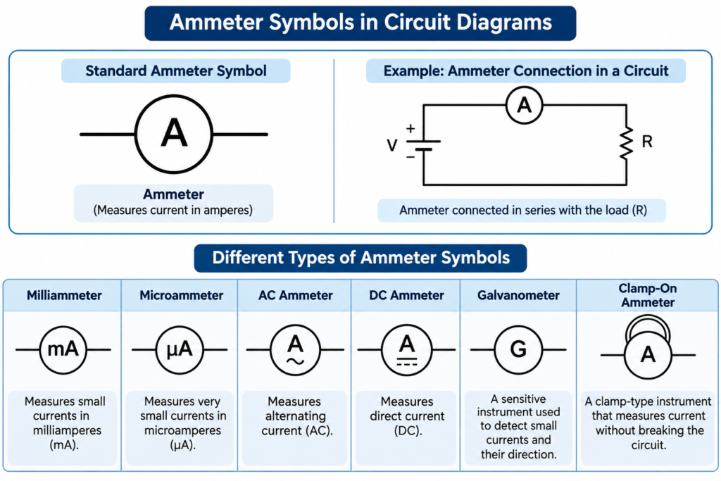
Different Types of Ammeter Symbols
The basic ammeter symbol can be modified to indicate the type of current measurement or the measuring instrument used.
- Milliammeter (mA): A circle containing the letters mA represents an instrument designed to measure small currents in milliamperes.
- Microammeter (µA): A circle marked µA indicates an instrument used for measuring very small currents in microamperes.
- AC Ammeter: A circle containing A along with a tilde (~) or AC marking indicates an instrument intended for measuring alternating current.
- DC Ammeter: A circle containing A with a straight-line and dashed-line marking indicates an instrument designed for measuring direct current.
- Galvanometer (G): A circle containing the letter G represents a sensitive instrument used to detect small electrical currents and their direction.
- Clamp-On Ammeter: A clamp-type current measuring instrument may be represented by an ammeter symbol with an additional marking or drawing indicating its magnetic clamp.
Note: The circle containing A is the widely used basic circuit symbol. Additional markings may vary depending on the drawing convention and the applicable IEC or ANSI standard.
Working Principle of Ammeter
The basic working principle of an ammeter is based on the magnetic effect of electric current. When current flows through a conductor or coil, it produces a magnetic field. This magnetic field interacts with another magnetic field or sensing element to produce a mechanical movement or an electrical signal that indicates the current value.
An ammeter is always connected in series with the circuit because the same current flowing through the branch must pass through the measuring instrument.
The internal resistance of an ammeter is kept very low so that it produces only a small voltage drop across its terminals. This voltage drop is known as burden voltage.
An ideal ammeter has zero internal resistance, whereas a practical ammeter has a small but finite resistance.
Why Is an Ammeter Connected in Series?
An ammeter is connected in series for the following reasons:
- The same current flows through all components connected in a series path.
- It allows the entire branch current to pass through the measuring element.
- Its low internal resistance minimises the effect on circuit operation.
Important safety precaution: Never connect an ammeter directly across a voltage source or electrical component while its leads are connected to the current terminals. Such a parallel connection can cause excessive current, blow the meter fuse, damage the instrument, or create an electrical hazard.
Always select the correct current terminal and measurement range before connecting the instrument. Where required, isolate the supply before opening the circuit and inserting the ammeter in series.
Classification or Types of Ammeter
Ammeters are classified according to their operating principle, measuring mechanism, and the type of current they measure.
The main types of analogue ammeters are:
- Permanent Magnet Moving Coil (PMMC) Ammeter
- Moving Iron (MI) Ammeter
- Electrodynamometer Type Ammeter
- Rectifier Type Ammeter
Based on the type of current measured, ammeters are classified as:
- DC Ammeter
- AC Ammeter
Digital ammeters are another important category. They use electronic sensing and signal-processing circuits to display current readings numerically.
1. Permanent Magnet Moving Coil (PMMC) Ammeter
A Permanent Magnet Moving Coil (PMMC) ammeter is an instrument primarily used for measuring direct current (DC). It operates on the principle that a current-carrying coil placed in a magnetic field experiences a mechanical force.
Working Principle of PMMC Ammeter
A Permanent Magnet Moving Coil (PMMC) ammeter operates on the principle that a current-carrying coil experiences a mechanical torque when placed in the magnetic field of a permanent magnet. This torque causes the coil and its attached pointer to rotate against the controlling force of a spring.
Explanation: When DC flows through the moving coil, the interaction between the magnetic field of the permanent magnet and the magnetic field produced by the coil generates a deflecting torque. The pointer moves across the calibrated scale until the deflecting torque is balanced by the controlling torque of the spring.
The deflecting torque is directly proportional to the current flowing through the coil. Therefore, the pointer deflection is proportional to the measured current, resulting in a nearly uniform scale.
The deflecting torque is expressed as:
Where:
- = Deflecting torque in N·m
- = Number of turns in the coil
- = Magnetic flux density in tesla (T)
- = Current through the coil in amperes
- = Area of the coil in square metres
The controlling spring produces an opposing torque. At equilibrium, the deflecting torque becomes equal to the controlling torque.
Since the deflecting torque is directly proportional to the current, the PMMC ammeter has a nearly uniform scale.
A conventional PMMC instrument measures DC only. If AC is applied, the direction of current reverses during every half-cycle, causing the deflecting torque to reverse as well. Consequently, the average torque over a complete cycle is approximately zero, and the pointer cannot provide a steady reading.
The PMMC mechanism is also known as a D’Arsonval movement. It offers high sensitivity, good accuracy, and low power consumption. However, it requires correct polarity and protection against excessive current.
Extension of Range of PMMC Ammeter
The measuring range of a PMMC ammeter can be extended by connecting a low-resistance shunt in parallel with its moving coil. The shunt provides an alternative path for the current, allowing most of the circuit current to bypass the sensitive measuring movement.
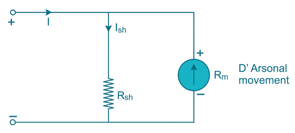
Only a small, predetermined portion of the total current passes through the moving coil, while the remaining current flows through the shunt. This arrangement enables the instrument to measure currents much higher than its original full-scale range.
The shunt resistance must be accurately selected according to the rated current of the moving coil and its voltage drop. Its current-carrying and power-dissipation capacities must also be adequate to prevent overheating and measurement errors.
The shunt resistance is calculated using:
Where:
- = Shunt resistance in ohms
- = Full-scale current of the movement in amperes
- = Resistance of the moving coil in ohms
- = Desired full-scale current of the ammeter in amperes
This arrangement allows a low-current PMMC movement to measure much higher currents.
Advantages of PMMC Ammeter
- High measurement accuracy and sensitivity.
- Nearly uniform scale.
- Low power consumption.
- High torque-to-weight ratio.
- Good damping characteristics.
Disadvantages of PMMC Ammeter
- Directly measures DC only.
- Relatively expensive compared with moving-iron instruments.
- Sensitive to overload and mechanical damage.
- Permanent magnet strength may change with ageing and temperature.
2. Moving Iron (MI) Ammeter
A Moving Iron (MI) ammeter is an electrical measuring instrument used to measure both alternating current (AC) and direct current (DC).
It operates on the principle that a soft-iron element experiences a mechanical force when placed in the magnetic field produced by a current-carrying coil.
Moving-iron instruments are commonly classified into two types:
- Attraction type MI ammeter.
- Repulsion type MI ammeter.
Working Principle of MI Ammeter
When current flows through the fixed coil of an MI ammeter, it produces a magnetic field. This field magnetises the soft-iron element and produces a deflecting torque.
The movement of the iron element rotates the pointer over the calibrated scale.
The deflecting torque is approximately proportional to the square of the current:
Where:
- = Deflecting torque
- = Current flowing through the coil
- = Inductance of the coil
- = Angular deflection of the moving element
Since the torque depends on the square of the current, its direction remains the same even when the current reverses. Therefore, an MI ammeter can measure both AC and DC.
Attraction Type MI Ammeter
In an attraction-type instrument, a small soft-iron vane is placed near or inside the fixed current-carrying coil.
When current flows through the coil, the iron vane is attracted towards the region of stronger magnetic flux. This movement operates the pointer and indicates the current value.
Repulsion Type MI Ammeter
A repulsion-type instrument contains two soft-iron vanes, one fixed and the other movable.
When current flows through the coil, both iron vanes become magnetised with the same polarity. The resulting repulsive force causes the movable vane to rotate and move the pointer.
Advantages of MI Ammeter
- Measures both AC and DC.
- Simple and robust construction.
- Suitable for industrial applications.
- Can withstand comparatively higher overloads than delicate PMMC movements.
Disadvantages of MI Ammeter
- Non-uniform scale, particularly at the lower end.
- Lower accuracy compared with PMMC instruments.
- Affected by hysteresis and stray magnetic fields.
- AC readings may be influenced by frequency and waveform.
3. Electrodynamometer Type Ammeter
An electrodynamometer-type ammeter is used to measure both AC and DC. It operates on the interaction between the magnetic fields produced by fixed and moving current-carrying coils.
Unlike PMMC and moving-iron instruments, an electrodynamometer instrument uses air-cored coils and does not depend on a permanent magnet or an iron magnetic circuit.
Working Principle of Electrodynamometer Ammeter
An electrodynamometer ammeter operates on the principle of interaction between the magnetic fields produced by two current-carrying coils. The instrument consists of fixed coils and a movable coil. In an ammeter arrangement, these coils are connected in series so that the same current flows through both.
Explanation: When current passes through the fixed and moving coils, their magnetic fields interact and produce a deflecting torque. This torque causes the movable coil and its attached pointer to rotate over the calibrated scale.
The deflecting torque is proportional to the product of the currents flowing through the two coils and can be expressed as:
The torque can be expressed as:
Where:
- = Deflecting torque
- = Current through the fixed coil
- = Current through the moving coil
- = Mutual inductance between the coils
- = Angular deflection
Since both coils are connected in series, their currents are equal and in phase. Therefore, the deflecting torque is proportional to the square of the current.
In the case of AC, the current in both coils reverses simultaneously during every half-cycle. Consequently, the direction of the interacting magnetic fields reverses together, and the torque continues to act in the same rotational direction. This enables the instrument to measure both AC and DC.
Advantages of Electrodynamometer Ammeter
- Measures both AC and DC.
- Does not suffer from iron hysteresis errors.
- Provides good accuracy when properly designed and calibrated.
- Can be used as a transfer instrument for comparing AC and DC measurements.
Disadvantages of Electrodynamometer Ammeter
- Relatively expensive construction.
- Low torque-to-weight ratio.
- Sensitive to external magnetic fields.
- Higher power consumption than some other instrument types.
- Friction can affect measurement accuracy.
4. Rectifier Type Ammeter
A rectifier-type ammeter is primarily used for measuring alternating current. It combines a rectifier circuit with a Permanent Magnet Moving Coil (PMMC) measuring mechanism.
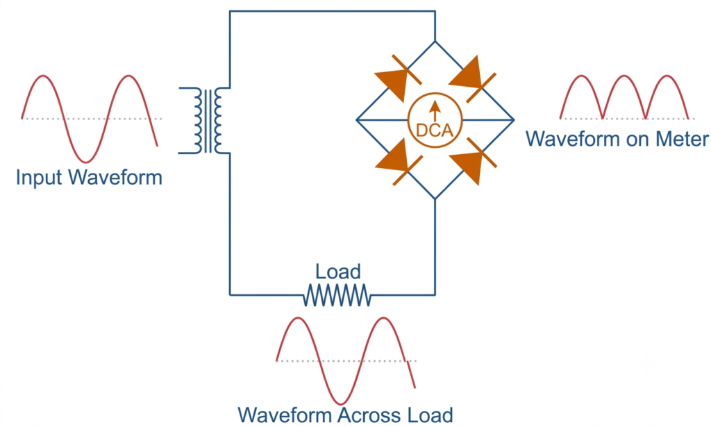
A PMMC movement cannot directly measure alternating current because the torque reverses with the direction of current. A rectifier solves this problem by converting AC into unidirectional current.
Working Principle of Rectifier Ammeter
A rectifier-type ammeter operates on the principle of converting alternating current (AC) into unidirectional current so that it can be measured using a Permanent Magnet Moving Coil (PMMC) movement.
Explanation: When AC flows through the rectifier circuit, semiconductor diodes convert the alternating waveform into a pulsating unidirectional current. This rectified current passes through the PMMC movement and produces pointer deflection, indicating the magnitude of the measured current.
For measuring higher AC currents, the rectifier circuit may receive its input from the secondary winding of a suitably rated current transformer (CT). In lower-current instruments, the rectifier is generally connected through an appropriate internal measuring circuit.
The instrument is usually calibrated to indicate the RMS value of a sinusoidal AC waveform. However, its measuring mechanism responds to the average value of the rectified waveform. Therefore, waveform distortion, diode voltage drop, and operating frequency can introduce errors in the indicated reading.
Advantages of Rectifier Ammeter
- Can measure AC using a PMMC movement.
- Provides a relatively uniform scale.
- Offers good sensitivity.
- Suitable for electronic and electrical measurement applications.
Disadvantages of Rectifier Ammeter
- Accuracy depends on the waveform of the measured current.
- Diode characteristics can introduce measurement errors.
- Frequency limitations affect performance.
- Low-current measurements may be affected by diode voltage drop.
5. Digital Ammeter
A digital ammeter measures electric current and displays the measured value in numerical form. It uses electronic sensing circuits and signal-processing techniques instead of a mechanical pointer.
Digital ammeters are widely used in electrical panels, electronic equipment, laboratories, battery systems, and industrial monitoring applications.
Working Principle of Digital Ammeter
A digital ammeter measures current by sensing the voltage developed across a known low-resistance shunt or by using another suitable current-sensing element.
The resulting voltage signal is processed by an electronic circuit and converted into a digital value using an analogue-to-digital converter (ADC).
The measured current is then displayed on an LCD or LED screen.
For a shunt-based digital ammeter, current is calculated using Ohm’s law:
Where:
- = Measured current in amperes
- = Voltage across the shunt in volts
- = Shunt resistance in ohms
Some digital ammeters use Hall-effect sensors or current transformers, depending on the application and current range.
Advantages of Digital Ammeter
- Clear numerical display.
- High resolution and good accuracy.
- Easy reading without pointer interpretation.
- Can provide additional functions such as data logging and overload indication.
- Available in compact panel-mounted and portable designs.
Disadvantages of Digital Ammeter
- Requires an external or internal power supply, depending on the design.
- Electronic circuits can be affected by electrical interference.
- Accuracy depends on calibration and the quality of the sensing circuit.
- Some models have limited measurement bandwidth.
6. Clamp-On Ammeter
A clamp-on ammeter operates on the principle of electromagnetic induction or the magnetic effect of electric current. It measures current by detecting the magnetic field produced around a conductor without requiring the electrical circuit to be disconnected.
Working Principle: The instrument has a pair of hinged jaws that can be opened and placed around a single current-carrying conductor. The current flowing through the conductor produces a magnetic field, which is detected by a sensor inside the jaws. The instrument processes this magnetic signal and displays the corresponding current value.
Depending on its design, a clamp meter may use a current transformer (CT), a Hall-effect sensor, or another magnetic sensing element. CT-based clamp meters generally measure AC, while Hall-effect models can measure both AC and DC.
Clamp-on ammeters are particularly useful for measuring current in operating electrical installations, motors, distribution panels, and industrial equipment because the circuit does not need to be opened.
7. Thermal Ammeter
A thermal ammeter operates on the heating effect of electric current, also known as Joule heating. When current flows through a resistance element, electrical energy is converted into heat, producing a temperature rise that depends on the current flowing through the element.
Working Principle: The instrument contains a fine resistance wire or heating element connected in series with the circuit. When current passes through this element, heat is generated due to its electrical resistance. The resulting temperature rise causes expansion of the wire or operates a temperature-sensitive element, such as a thermocouple.
In a thermocouple-based thermal ammeter, the heat generated by the current produces a small thermoelectric voltage. This voltage is measured by a sensitive meter movement and calibrated to indicate the current value.
Since the heating effect depends on the square of the current, thermal ammeters can measure both AC and DC. They are particularly useful for measuring high-frequency currents because their operation is based on the heating effect rather than the magnetic response of a conventional moving-coil mechanism.
However, thermal ammeters generally have a slower response because the heating element requires time to reach thermal equilibrium. They are also affected by ambient temperature and heat loss.
Types of Ammeter Based on Current
Ammeters can also be classified according to whether they measure direct current or alternating current.
DC Ammeter
A DC ammeter is designed to measure the magnitude of direct current flowing through a circuit.
The current flows in one direction, so the instrument indicates a steady current value for a steady DC supply.
PMMC instruments are commonly used for DC current measurement because of their high accuracy, sensitivity, and uniform scale.
A suitable shunt can be connected in parallel with the PMMC movement to extend its measuring range.
Applications of DC Ammeter
- Battery charging and discharging systems.
- DC motor circuits.
- Solar photovoltaic installations.
- DC power supplies.
- Electronic circuits and control panels.
AC Ammeter
An AC ammeter is designed to measure alternating current, which periodically changes its magnitude and direction.
Moving-iron and electrodynamometer instruments can measure AC directly. Rectifier-type instruments use a rectifier with a PMMC movement, while modern digital ammeters use electronic sensing techniques.
AC ammeters are commonly calibrated to indicate the RMS value of current.
Applications of AC Ammeter
- AC motor circuits.
- Electrical distribution panels.
- Transformer circuits.
- Industrial power systems.
- Alternating-current generators.
Comparison Between Different Types of Ammeters
The following table highlights the major differences between commonly used ammeters.
| Type of Ammeter | Operating Principle | AC Measurement | DC Measurement | Scale |
| PMMC | Magnetic effect of current | No, not directly | Yes | Uniform |
| Moving Iron | Magnetic attraction or repulsion | Yes | Yes | Non-uniform |
| Electrodynamometer | Interaction of magnetic fields | Yes | Yes | Generally non-uniform |
| Rectifier Type | AC rectification with PMMC movement | Yes | Possible in suitable designs | Nearly uniform |
| Digital | Electronic current sensing | Yes, depending on design | Yes, depending on design | Numerical display |
Difference Between AC Ammeter and DC Ammeter
| Parameter | AC Ammeter | DC Ammeter |
| Current measured | Alternating current | Direct current |
| Current direction | Changes periodically | Remains in one direction |
| Common instrument | MI and electrodynamometer | PMMC |
| Reading | Generally RMS value | Average or steady DC value |
| Polarity | Usually not polarity-sensitive | Polarity must be observed in polarised instruments |
| Applications | AC distribution and motors | Batteries and DC systems |
| Parameter | AC Ammeter | DC Ammeter |
|---|---|---|
| Current measured | Alternating current | Direct current |
| Current direction | Changes periodically | Remains in one direction |
| Common instrument | MI and electrodynamometer | PMMC |
| Reading | Generally RMS value | Average or steady DC value |
| Polarity | Usually not polarity-sensitive | Polarity must be observed in polarised instruments |
| Applications | AC distribution and motors | Batteries and DC systems |
Important Characteristics of an Ammeter
Several characteristics determine the performance and suitability of an ammeter.
1. Internal Resistance
The internal resistance of an ammeter is kept very low to minimise voltage drop and avoid disturbing the circuit current.
2. Measuring Range
The measuring range specifies the minimum and maximum current that an instrument can measure accurately.
3. Accuracy
Accuracy indicates how closely the displayed reading corresponds to the actual current flowing through the circuit.
4. Resolution
Resolution is the smallest change in current that the instrument can detect and display.
5. Burden Voltage
Burden voltage is the voltage drop developed across an ammeter during current measurement. A lower burden voltage generally results in less disturbance to the circuit.
6. Overload Protection
Overload protection safeguards the measuring instrument against excessive current. Digital handheld ammeters commonly use fuses for this purpose.
Applications of Ammeter
Ammeters are used in a wide range of electrical and electronic applications.
- Electrical distribution panels: To monitor current flowing through incoming and outgoing feeders.
- Industrial motors: To measure motor current and identify abnormal loading conditions.
- Power generation: To monitor generator output current.
- Transformer systems: To measure primary and secondary currents using suitable measuring arrangements.
- Battery systems: To monitor charging and discharging current.
- Solar power systems: To measure current generated by photovoltaic panels.
- Electrical laboratories: To perform experiments and verify electrical circuit calculations.
- Electronic equipment: To measure current consumption in electronic circuits and power supplies.
Conclusion
An ammeter is an essential electrical measuring instrument used to determine the current flowing through a circuit. Its basic working principle involves converting the magnetic or electrical effect of current into a readable indication.
PMMC, moving-iron, electrodynamometer, rectifier-type, and digital ammeters are commonly used for different measurement requirements. PMMC instruments are suitable for accurate DC measurements, while MI and electrodynamometer instruments can measure both AC and DC.
The correct selection of an ammeter depends on the current range, supply type, accuracy requirements, and operating conditions. Proper series connection and suitable overload protection are also essential for safe and reliable current measurement.
Read Next:
- Clamp Meter Working Principle, Diagram & Uses
- Difference Between Indicating and Recording Instruments
- Null Type Instrument: Principle, Example, and Key Advantages
- Types of Measuring Instruments in Electrical Engineering
- Integrating Instruments: Classifications, Advantage and Applications
- Digital Instruments: Definition, Characteristics, Construction, Advantages, and Disadvantages
- Analog Instruments: Definition, Classification, and Working Principle