Learn about the speed control of DC series motor, including methods like field diverter, armature resistance, tapped field, and thyristor control. Discover how speed control in DC motors works with diagrams, advantages, and FAQs.
What is the Speed Control of DC Series Motor?
Speed control of a DC series motor refers to the ability to vary the speed of the motor to suit different applications. DC series motors are known for their high starting torque, making them ideal for applications such as electric trains, cranes, and hoists. However, controlling their speed is more complex than other types of DC motors due to the series connection of the armature and field winding.
To maintain performance and ensure safety, several methods of dc motor speed control are used, especially when working with dc series motor speed control systems.
Why Speed Control in DC Motor is Important?
Speed control in DC motors allows:
- Better performance in variable load applications.
- Energy savings by running the motor at optimal speed.
- Precision in automation and industrial systems.
Especially in the case of DC series motors, where load variations are common, controlling the speed is essential.
Speed Control Methods of DC Series Motor
The speed of a DC series motor is given by the equation:
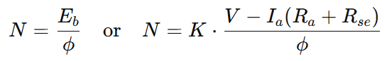
Where:
- N = Speed of the motor
- Eb = Back EMF
- ϕ = Magnetic flux
- V= Supply voltage
- Ia = Armature current
- Ra = Armature resistance
- Rse = Series field resistance
- K = Motor constant
From the above formula, it is clear that the speed of a DC series motor can be controlled by changing either the back EMF or the magnetic flux. This leads to two main methods of speed control in a DC series motor:
- Field Control Method
- Armature Resistance Control Method
These methods fall under the general category of speed control for DC motors, each with its specific application and speed range.
Field Control Method:
The Field Control Methods for DC series motors include the Field Diverter Method, Armature Diverter Method, and Tapped Field Control Method.
1. Field Diverter Method
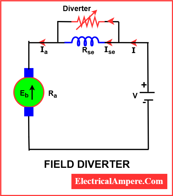
In this dc motor speed control method, a variable resistor (field diverter) is connected in parallel with the series field winding. This resistor diverts part of the current away from the field winding, reducing the magnetic field strength. As a result, the motor speed increases.
Since motor speed is inversely proportional to the field strength, reducing the field increases speed.
Key Points:
- Speed increases with reduced field strength.
- Simple and cost-effective.
- Used for obtaining higher than normal speed.
The lowest speed achievable with this method is when no current flows through the diverter, which corresponds to the normal rated speed of the motor. Hence, the field diverter method is only effective for increasing the speed above normal.
This technique is commonly used in traction applications, where variable and higher speeds are often required.
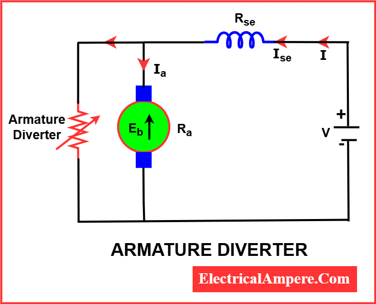
2. Armature Diverter
In this method, a variable resistance, known as an armature diverter, is connected in parallel with the armature winding. This setup diverts a portion of the line current away from the armature, effectively reducing the armature current and altering the motor’s speed.
Formula:
Where:
- N = Speed of the motor
- V = Supply voltage
- Ia = Armature current
- Ra = Armature resistance
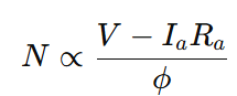
- ϕ = Field flux
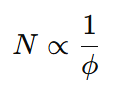
For a given load, if the armature current (Ia) is reduced, the flux must increase to maintain constant load torque, since torque (τa) ∝ Ia. Because motor speed (N) is inversely proportional to flux (ϕ), i.e., N ∝ 1/ϕ, an increase in flux results in a decrease in motor speed. Therefore, by using the armature diverter method, it is possible to obtain motor speeds lower than the normal speed.
Key Points:
- Useful for lower than normal speeds.
- Simple but inefficient due to power loss in the resistor.
- Poor speed regulation.
3. Tapped Field Control Method
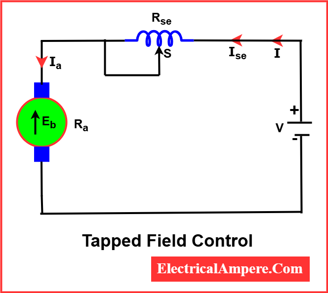
In this method, the field winding is divided into several sections with taps, allowing the user to change the number of turns in the field circuit. Reducing the number of turns decreases the field strength, thus increasing the motor speed.
A switch (S) is used to short-circuit a portion of the series field winding, as shown in the figure. When the entire field winding is in the circuit, the motor runs at its normal speed. However, by reducing the number of active turns in the series field winding, the field strength weakens, which allows the motor to run at speeds above the normal speed.
Key Points:
- Discrete speed levels can be achieved.
- Commonly used in electric traction.
- Efficient and offers improved performance compared to field diverter method.
Armature Resistance Control Method
In the armature resistance control method, a variable resistor is connected in series with the supply line, completing the motor circuit (as illustrated in the diagram).
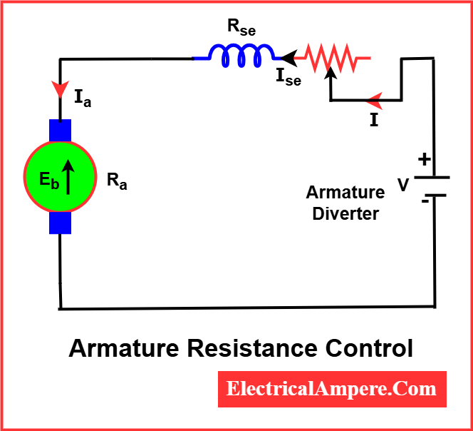
This added resistance lowers the voltage across the armature, which in turn reduces the motor speed. By adjusting the value of this series resistance, any speed below the normal operating speed can be achieved.
Although this method offers poor speed regulation, it is widely accepted in applications where speed variation is not only acceptable but necessary—such as in traction systems and cranes. Due to its simplicity and ease of implementation, the armature resistance control method remains one of the most commonly used techniques for controlling the speed of DC series motors.
Armature Voltage Control Using Thyristors
This modern method involves using a thyristor-based DC drive to control the voltage applied to the motor’s armature. By adjusting the armature voltage, the speed can be precisely regulated.
Key Points:
- Smooth and precise speed control.
- Highly efficient and reliable.
- Suitable for automation systems and modern industrial drives.
Comparison of DC Series Motor Speed Control Methods
| Method | Speed Range | Efficiency | Complexity | Applications |
|---|---|---|---|---|
| Field Diverter | Above normal speed | Moderate | Simple | Traction systems, cranes |
| Armature Diverter | Below normal speed | Low | Simple | Hoists, elevators |
| Tapped Field Control | Step-wise above normal | Moderate | Moderate | Electric trains, tramways |
| Armature Resistance Control | Below normal speed | Low (due to losses) | Simple | Electric traction, industrial motors |
| Thyristor Armature Voltage Control | Wide speed range | High | Complex | Precision drives, automated machinery |
Applications of Speed Control in DC Series Motors
- Electric locomotives
- Elevators and hoists
- Industrial cranes
- Traction systems
- Fans (in specific configurations)
Numerical Example
A 350 V DC series motor operates at 1200 RPM while drawing a line current of 60 A. The armature resistance is 0.06 Ω and the series field resistance is 0.04 Ω. If the motor continues to draw the same current, calculate the value of the additional series resistance required to reduce the speed to 1000 RPM.
To solve this problem, we’ll use the formula for speed of a DC series motor, where:

For a DC series motor, flux (ϕ) is approximately proportional to armature current (Ia) when magnetic saturation is not present. Since the current remains constant (60 A), flux is also constant, and we can write:
Given:
- V=350 V
- N1=1200 RPM
- N2=1000 RPM
- Ia=60 A
- Ra=0.06 Ω
- Rse=0.04 Ω
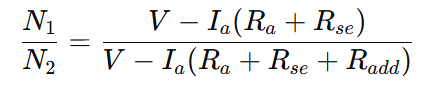
Step 1: Apply the speed ratio formula
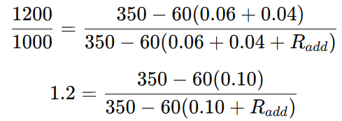
Let’s simplify and solve for Radd.
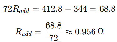
The additional series resistance required to reduce the motor speed to 1000 RPM is approximately 0.956 Ω.
Conclusion
Understanding the speed control of DC series motor is crucial for optimizing performance in applications where varying loads and speed demands are common. With a mix of traditional and modern DC motor speed control methods, engineers can design reliable and efficient systems. Whether you’re looking to improve torque, efficiency, or precision, the right speed control method makes all the difference in speed control for DC motor applications.
For a broader understanding of how DC series motors function, visit our main article: DC Series Motor – Construction, Working & Applications
FAQs on Speed Control of DC Series Motor
Voltage control using electronic controllers is generally the most efficient and offers precise speed regulation.
No, running a DC series motor without load is unsafe as it may lead to dangerously high speeds and potential motor damage.
The main methods include flux control, armature resistance control, and voltage variation using series-parallel or electronic controllers.
For DC series fan motors, armature resistance control or field diverter methods are commonly used, as they are cost-effective and provide acceptable control for fan-type loads.
The speed of a DC series motor is controlled using various methods such as field diverter, armature resistance, tapped field control, and thyristor-based armature voltage control. Each method alters the voltage, current, or magnetic flux to achieve the desired speed.
Related Articles: