What is Core Balance Current Transformer?
A Core Balance Current Transformer (CBCT) is a special type of current transformer. It has a magnetic coil wound on a ring-shaped core, which acts as a backup coil. The conductors passing through the ring-shaped core act as a primary winding of CBCT.
A Core Balance Current Transformer is crucial for electrical protection systems. It works as current sensor and detects imbalance currents in a circuit and gives an output. These imbalance currents are caused by earth faults, earth leakage, or ground faults in the system. The imbalance current is also called zero sequence current. CBCT detects the imbalance current or zero sequence current, therefore it is called a Zero Sequence Current Transformer(ZCT).
It serves as a protection device and outputs a signal to an earth fault relay when a fault occurs. The earth fault relay issues a trip command to a circuit breaker to break the circuit.
The secondary coil, with the maximum number of turns, forms a circular ring in the Core Balance Current Transformer (CBCT). This ring encloses either three single-core cables or a single three-core wire of a three-phase system. The three-phase wire system serves as the primary winding of the CBCT. When an imbalance current occurs in the system, it generates a magnetic field in the circular ring. This magnetic field induces a current in the secondary winding, which is then used for fault detection and protection.
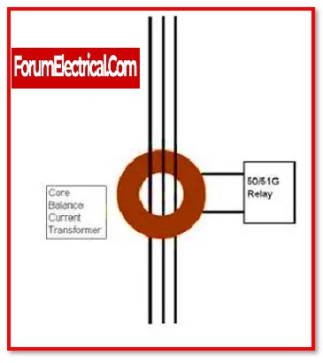
In the below diagram, the CBCT is a current transformer through which all three-phase currents flow.
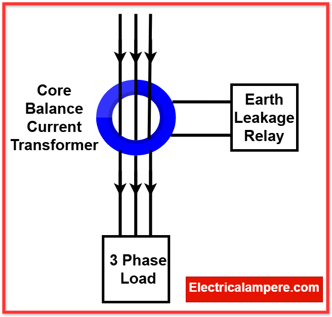
The magnetic fluxes of the three-phase currents cancel each other out. As a result, the net magnetic flux is zero. When all three phases are healthy, no current flows in the transformer’s secondary winding, so the CBCT’s secondary current is zero.
However, if an earth fault occurs in one of the phases, the zero-sequence fault current flows. This current is not canceled by the flux of the other two phases. As a result, a current is induced in the CBCT’s secondary winding. An earth fault relay connected to the CBCT can use this secondary current to generate a tripping signal for protection.
Working principle of a Core Balance Current Transformer (CBCT)
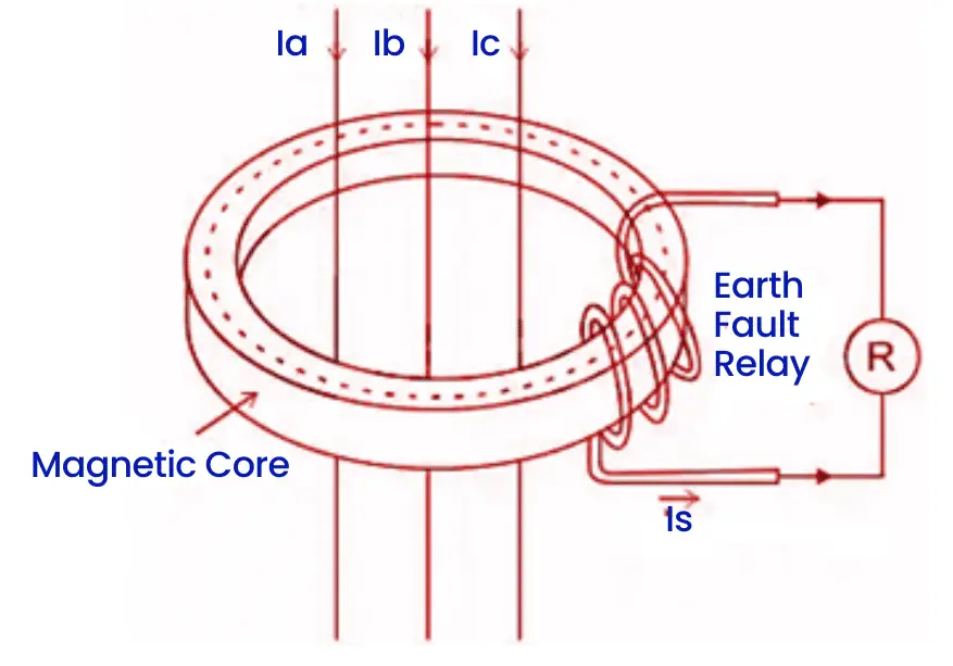
Image Source: Electricalvolt
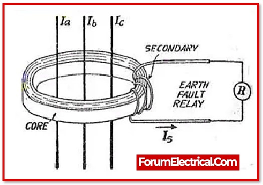
The image above shows the use of CBCT in a circuit. The three-phase currents are labeled as Ia, Ib, and Ic. The primary consists of these three-phase wires. The secondary winding is connected to a relay for protection. The working principle of current transformers is based on zero-sequence current balance. For this reason, it is also called a Zero Sequence Current Transformer (ZCT).
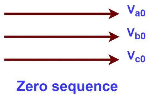
In a three-phase system, zero-sequence voltage or current happens when all three phases have equal and symmetrical voltages or currents. When all the values in a zero-sequence system add up to zero, the system is balanced. This is similar to Kirchhoff’s current law, which says the total current at a node equals zero.
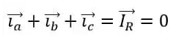
In normal operation, the sum of the phase currents equals zero.
In the absence of a fault, the residual current is zero, which means the zero-sequence current is also zero. This occurs because the system is balanced, and no unbalanced currents are present. Since the residual current is directly proportional to the corresponding current, the magnetic field flux generated by the residual current is also zero.
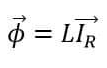
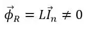
Where,
Φ – generated magnetic field flux
IR – Resultant current
L – Inductance coil
The current and magnetic field flux are directly proportional to each other. In this case, the magnetic field flux generated by the primary winding, which interacts with the secondary winding of the Core Balance Current Transformer (CBCT), is zero because the residual current is zero. As a result, no magnetic flux is induced in the secondary winding of the CBCT, and no current flows through it.
Let Ia, Ib, and Ic, respectively, be the phase currents, and let Φa, Φb, and Φc be the resulting magnetic fields.
Let Ia, Ib, and Ic represent the phase currents, and let Φa, Φb, and Φc represent the corresponding magnetic fields.
Therefore,
When this magnetic field interacts with the secondary winding of the Core Balance Current Transformer (CBCT), a small current flows through the secondary coil. This current is sent to a relay, which detects the imbalance and activates. Upon activation, the relay transmits a trip signal to the circuit breaker. The circuit breaker then disengages, isolating the fault zone and cutting off the power supply to prevent further damage.
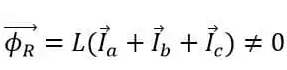
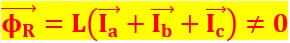
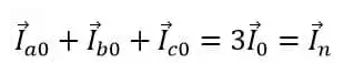
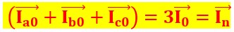
The magnitude and phase of the zero-sequence currents are the same. As a result, the resulting zero-sequence current is their sum.
This current is not zero during fault or unbalanced current in the system. It generates the magnetic field required for the CBCT to operate effectively.
Under normal conditions, the system is balanced, so the total zero-sequence current is zero. Consequently, no magnetic field flux is generated.
Selection of Core Balance Current Transformer (CBCT)
The proper selection of a Zero Sequence CT (or Core Balance CT (CBCT) is based on several critical parameters for accurate fault detection. These parameters are detailed below:
- Nominal CT Ratio
The CT ratio must be carefully chosen to ensure that even the smallest ground fault produces a current high enough to activate the earth fault relay. This ratio is essential for the sensitivity and reliability of fault detection. - Primary (Main) Ground Leakage Current
The ground leakage current must be minimized to reduce false tripping and enhance the accuracy of the system. Proper grounding and minimal leakage ensure effective and stable operation. - Relay Operating Voltage and Minimum Excitation Current
The relay associated with the CT requires a specific operating voltage for activation. The CT must supply sufficient current to meet the relay’s excitation requirements without delay. - Voltage at the Fault Point
The voltage present at the fault location plays a significant role in determining the CT’s ability to sense and relay the fault accurately. It should align with the CT’s specifications for fault detection. - CT Dimensions and Internal Diameter
The physical dimensions and internal diameter of the CT are critical, as they must accommodate the cables passing through them. The internal diameter varies depending on the cable size, and this must be considered during selection to avoid mechanical issues. - System Configuration and Load Characteristics
The CT should be compatible with the system’s load characteristics and configuration, ensuring no compromise on measurement accuracy or relay operation. - Environmental Conditions
The operating environment, including temperature, humidity, and exposure to contaminants, must be considered. The CT should have the necessary insulation and protection to perform reliably in its intended environment.
Characteristics of Core Balance Current Transformer (CBCT)
Core Design
The conductor is surrounded by a ring-shaped toroidal core. This toroidal core allows the CBCT to measure current without making contact to the conductor. This non-intrusive design ensures efficiency and reliability.
Accuracy
CBCTs provide very accurate measurements, with errors less than 1%. This high accuracy is maintained across a wide range of currents and frequencies.
Easy Installation
CBCTs are easy to install without disconnecting the power supply. The CBCT can be clamped around the conductor.
Safety
CBCTs are safe because they do not require a direct connection to the conductor. This design of CBCT minimizes the risk of electrical shock and prevents the introduction of additional electrical noise into the system.
Output Signal
The output signal from a CBCT is directly proportional to the current flowing through the conductor. This signal is used for multiple purposes, such as monitoring system performance, controlling equipment, and providing protection in electrical systems.
Variety in Sizes
CBCTs come in various sizes. Compact core balance CT is ideal for domestic and commercial applications, while larger ones are designed for industrial use that can handle higher current levels.
Cost
CBCTs are usually more affordable than traditional current transformers (CTs) because they do not require a solid core or secondary winding. This cost advantage makes them an attractive choice for many industries and applications.
Core Balance Current Transformer (CBCT) Specifications
A Core Balance Current Transformer (CBCT) is used primarily to detect leakage or ground fault currents. Its specifications include the following parameters:
- Primary Current (Rated): Generally, 0–1000 A or as per system requirements.
- Secondary Current: Standard values of 1 A or 5 A.
- Rated Frequency: 50 Hz or 60 Hz.
- Accuracy Class: Protection: 5P, 10P, Measurement: Class 1, Class 0.5
- Rated Burden: Varies (e.g., 5 VA, 10 VA, or as required by the system).
- Sensitivity: Designed for low-level current detection, e.g., 30 mA–3 A.
- Short-Time Current Rating: Defined in kA for 1 second.
- Core Material: High-permeability magnetic material, usually silicon steel or ferrite core.
- Window Diameter: Depends on cable size (e.g., 50 mm, 100 mm, or larger).
- Encapsulation: Epoxy resin or equivalent for insulation and environmental protection.
- Mounting Type: Fixed, portable, or split-core design.
- Ingress Protection (IP) Rating: Commonly IP54 or higher for outdoor use.
- Operating Temperature: Typically -25°C to +55°C.
- Storage Temperature: Typically -40°C to +70°C.
- Humidity: Up to 95% non-condensing.
- Applicable Standards: IEC 61869-2, IS 2705, or equivalent.
- Certifications: Relevant certifications for safety and performance.
- Earth Fault Detection: High sensitivity for detecting small leakage currents.
- Overload Capacity: Ability to handle transient currents without damage.
- Signal Output: Provisions for connecting to relays, meters, or data acquisition systems.
Difference between Core Balance Current Transformer(CBCT) and Current Transformer(CT)
A Core Balance Current Transformer (CBCT) and a standard Current Transformer (CT) are used for different purposes in electrical systems. CBCT detects ground faults or leakage currents by measuring the vector sum of all currents passing through its core. A CT measures the current in a single conductor for metering or overcurrent protection. While CBCT detects milliamps to a few amps of leakage current, a CT handles higher primary currents.
Advantages of Core Balance Current Transformer (CBCT)
- The main advantage of using CBCT for earth fault prevention is that it requires only one CT core, unlike traditional systems that use three CT cores.
- This reduces the magnetic flux required to generate the secondary current to one-third (1/3), and improves the measurement sensitivity.
Disadvantages of Core Balance Current Transformer (CBCT)
- The main disadvantage of a CBCT (Current Transformer) is that the conductor must be fully enclosed within the magnetic core. This makes it unsuitable for large conductors, as the transformer would become too large and hard to manage.
- CBCTs are less effective for applications with multiple conductors because they can only measure the current in one conductor at a time.
- Another disadvantage of CBCTs is that they cannot measure direct current (DC) since they only operate with alternating current (AC).
Applications of Core Balance Current Transformer (CBCT)
- CBCT is used in the motor protection circuit.
- CBCT is used for ground fault detection in electrical power systems.
- Core balance CT is used for leakage current monitoring.
- CBCT is used to monitor and analyze the power quality.
- CBCT is used to protect heavy electrical machinery.
Read Next: