As microprocessor technology improves, new features become available, and these features come at lower and lower costs. One example is electronic metering, also called metrology functionality. It is now included in point-of-use power protection devices. Metrology functionality includes several measurements. It can measure voltage and current. It can also measure instantaneous power consumption and energy usage. Some devices even include oscilloscope functionality.
A metrology IC often includes two important measurements. These are the Power Factor and Crest Factor. The purpose of this article is to define these measurements. It will explain how they help understand the power condition of a branch circuit. These measurements also provide useful information about connected electronic loads.
Power Factor
Power Factor can be defined in different ways. However, all definitions are interconnected. Before defining the Power Factor, we need to understand Power. Power is the rate at which electrical energy is converted into another form. This can be heat, mechanical energy, or stored energy in electric and magnetic fields. Power is calculated as Voltage (V) multiplied by Current (I). This gives the power consumed by an electronic load. In a DC (Direct Current) circuit, voltage is constant. The current is also constant. Since both values stay the same, the power consumed is also constant.
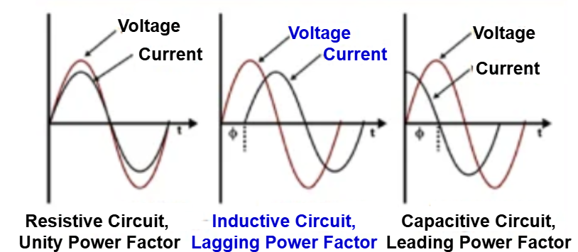
In an AC (Alternating Current) circuit, calculating power consumption is more complex. Unlike DC voltage, which is constant, AC voltage changes continuously in a sinusoidal pattern. Some electronic loads draw current at different points along the voltage waveform. Purely resistive loads draw current in a sinusoidal pattern. This pattern stays in sync with the voltage waveform.
However, more complex electrical loads behave differently. Capacitive or inductive loads do not draw current in sync with the voltage. In these cases, the peak current either leads or lags behind the peak voltage waveform.
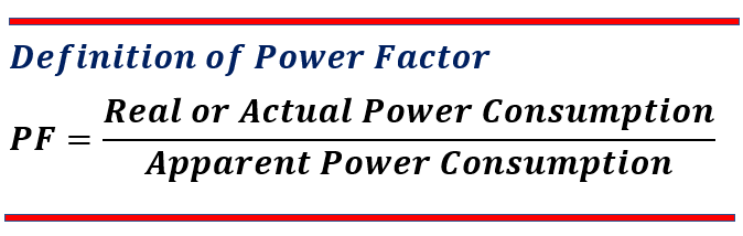
Real or actual power consumption is the power an electronic load uses to perform its function. It is measured in Watts. Apparent or total power is the power the electrical source must supply for the load to work. It is measured in Volt-Amps (VA). The power Factor is a value between 0 and 1. When the Power Factor is 1, Real Power equals Apparent Power. Power Factor indicates how efficiently a device uses the electrical power it receives. However, the Power Factor is not the same as efficiency. Efficiency is the ratio of Energy Out to Energy In.
In some cases, the current waveform is not sinusoidal.
When an electronic load does not draw current in a smooth sinusoidal pattern, it creates problems for the power company.
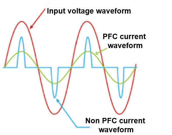
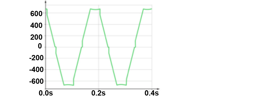
For example, the blue waveform below represents the current draw of a typical switch-mode power supply.
This type of power supply pulls current in short bursts, creating a high peak value. If we multiply this peak current by the corresponding peak voltage, the instantaneous power draw is very high. Now, consider billions of such power supplies running electronic devices worldwide. At each peak of the voltage waveform, the power company must supply a large amount of current. Since power plants must handle these peak demands, more such electronic devices mean a greater need for power plants.
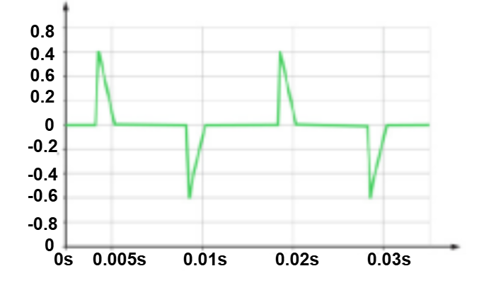
To reduce this burden, Power Factor Correction (PFC) circuitry is used. The green waveform below shows the current draw of the same switch-mode power supply, but with PFC added. With PFC, the peak current is about half of the Non-PFC current waveform. However, the average current draw remains the same for both PFC and Non-PFC power supplies. This means the load consumes the same total power in both cases. PFC helps by lowering the peak power demand while maintaining the same overall power consumption.
PFC circuitry benefits both the power company and the consumer. It reduces the instantaneous power demand, making it easier for the power grid to handle. For consumers, PFC can help lower electricity costs. Smart power meters often calculate rates based on peak power consumption, not just average consumption. By reducing peak consumption, PFC helps lower electricity bills.
Power Factor is also important when evaluating Uninterruptible Power Supplies (UPS). The PF rating of a UPS indicates how much Real Power it can provide. A higher PF rating means the UPS can deliver more usable power to connected devices.
Most companies rate their UPS based on Apparent Power (VA) instead of Real Power (Watts). This is because the Apparent Power rating is always a higher number.
However, the actual Real Power a UPS can deliver is calculated as:
Real Power = Apparent Power × Power Factor
For example, consider two UPS units:
- UPS A has a 2200 VA rating with a Power Factor of 0.75.
- UPS B has a 2050 VA rating with a Power Factor of 0.9.
At first glance, UPS A seems more powerful because of its higher VA rating. However, Real Power calculations will give the true comparison.
UPS A: 2200VA x 0.75 PF = 1650 Watts of Real Power Delivery
UPS B: 2050VA x 0.9 PF = 1845 Watts of Real Power Delivery
Measuring the Power Factor of a connected load can provide useful insights into equipment health. If the average Power Factor is known or tracked over time, any sudden change could signal a problem. A sharp drop in the Power Factor may indicate an issue with the load’s power supply. This could be an early warning of possible failure or malfunction.
Crest Factor
The Crest Factor (CF) is another important mathematical relationship used in electrical engineering. It helps analyze waveforms and their characteristics. In some cases, CF is used to determine the quality of a waveform. In other cases, it helps identify if a waveform has many peaks.
Crest Factor (CF) can be measured for any type of waveform, including square waves, triangle waves, and DC signals. For DC signals, the CF is always 1 because the Peak Value equals the Average Value. In AC power systems, voltage is generated as a sine wave. This makes CF calculation more complex compared to DC.
Root Mean Square (RMS) is a quantity used to determine the average value of a time-varying signal. For pure sine waves, the RMS value is calculated as:
RMS = Peak Value / √2
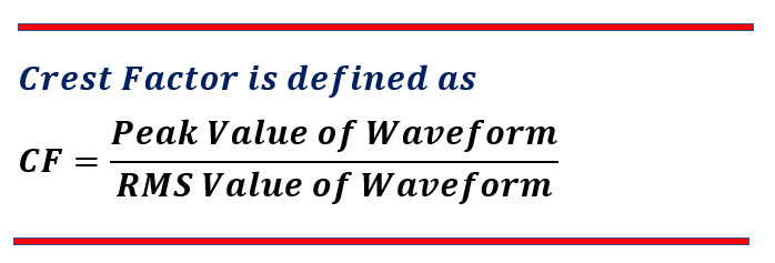
If the Peak Value is 1, then the RMS value is 0.707. By rearranging this formula, we can derive a theoretical Crest Factor (CF) that does not depend on the Peak Value. The crest factor formula is,

This means that for a perfect sine wave, the Crest Factor (CF) is always 1.414, regardless of its peak value. A pure sine wave cannot have a CF higher than 1.414.
The above explanation assumes a sinusoidal waveform, but CF can also be calculated for non-sinusoidal waveforms.
To measure CF accurately, a meter must be able to measure both the Peak Value and the True RMS Average Value of a waveform. Such meters are widely available. For non-sinusoidal waveforms, CF can be much higher than 1.414. A higher CF indicates that the waveform has peaks significantly greater than its RMS Average Value. This concept becomes important when comparing Voltage CF and Current CF.
Voltage Crest Factor
Voltage waveforms in power distribution systems start as sinusoidal. However, by the time they reach the point of use, they are often not perfect.
One common issue in AC electrical systems is called Flat-Topping. Flat-topping happens when the resistance of the branch circuit wiring is too high. This resistance depends on the length and gauge (thickness) of the wire. When high peak currents are drawn—like in a Non-PFC switch-mode power supply—the voltage waveform gets distorted. Instead of the entire sinusoidal voltage dropping proportionally, only the top part gets clipped off. This reduces the Peak Value of the voltage while the RMS value remains similar. As a result, the Voltage Crest Factor (CF) falls below 1.4.
Monitoring the Voltage Crest Factor (CF) is a useful way to detect wiring issues in a building. For example, if an unloaded electrical circuit has a Voltage CF close to 1.4, it indicates a healthy circuit. However, if plugging in an electronic load causes the Voltage CF to drop below 1.1, it could mean the circuit is near or beyond its power transfer limit. This problem often occurs when the wire length is too long for its gauge (thickness). The solution in such cases is to install a new wire with a larger gauge, which reduces resistance and improves power delivery.
Crest factor (CF) measurements help detect wiring and loading issues that a simple voltage check might miss. For example, a basic voltage measurement might show 115V, which seems normal for a 120V system (within -5% tolerance). However, if the CF measurement is 1.38–1.39, it suggests that the circuit is overloaded or underserved. This means that when equipment draws power at the voltage peaks, it may be experiencing more severe voltage drops than what the basic voltage reading shows.
Current Crest Factor
The voltage waveform in power distribution starts as a sine wave. However, the current drawn by electronic loads may not be sinusoidal.
Purely resistive loads pull sinusoidal current, matching the voltage waveform. But other loads, like switch-mode power supplies, draw non-sinusoidal current. As a result, Current CF values are often much higher than the 1.414 value seen for Voltage CF.
Current CF measurements are useful for analyzing electronic loads.
- If a load has a Current CF above 3, it likely lacks Power Factor Correction (PFC).
- This means it pulls current in peaks, rather than smoothly over the waveform.
Such loads increase stress on power systems and can lead to higher peak power demands.
Most circuit breakers used today are mechanical switches with a thermal trigger. The thermal trigger activates when it detects a continuous current above its trip point. Some electronic loads pull current in sharp peaks instead of a steady flow. These peak currents can heat up the thermal trigger and cause the breaker to trip unexpectedly. As a result, devices with a high Current Crest Factor (CF) may lead to unintended circuit breaker trips.
Current CF is also used to measure the performance of a UPS. CF is the ratio of Peak Value to RMS Average Value. A UPS with a high Current CF can supply enough current to loads. These loads may not be Power Factor Corrected and may pull current in peaks. If a UPS has a low Current CF, it may struggle with such loads. It may limit the current supply. This can distort the voltage waveform. As a result, the electronic load may experience unwanted harmonic distortion.
Summary
- The Power Factor of an electronic load is a number between 0 and 1. It indicates how efficiently the load uses the AC electrical supply. It does not measure how efficient the load is in terms of energy usage.
- Monitoring the Power Factor of an electronic load detects sudden changes. A significant change may indicate that the load is damaged or nearing failure.
- The Power Factor rating of a UPS shows the amount of true power it can supply.
- The Voltage Crest Factor in an AC power system indicates the quality of the voltage waveform delivered to the electrical load.
- The Voltage Crest Factor in an AC power system indicates how the circuit is loaded.
- The Current Crest Factor in an AC power system shows how an electronic load draws current.
- Loads with a high Current Crest Factor can accidentally trip circuit breakers.
- UPSs should have a high Current Crest Factor capability to supply current to all loads without distorting the voltage waveform.
Read Next: