Discover the various types of electrical diagrams and types of electrical drawing used in electrical engineering. Learn their purposes, features, and practical applications in this complete guide.
To accurately represent a specific electrical system or circuit in Electrical and Electronics Engineering, various types of drawings and diagrams are used. These diagrams depict electrical circuits using lines to represent wires and standardized symbols or icons to represent different electrical and electronic components.
These diagrams help in understanding the relationship between components within a system. For example, electricians use an electrical floor plan—also known as an electrical diagram—when wiring a building. This type of diagram illustrates the layout and connection of electrical devices and systems throughout a structure.
For operating and maintaining machinery, electrical drawings are essential as they show how electrical devices are interconnected. These drawings focus solely on the components and their connections, not necessarily the physical layout. Engineers may use different types of electrical drawings to emphasize specific parts of the system depending on the purpose, whether it’s installation, troubleshooting, or analysis.
Common Types of Electrical diagrams Include:
- Block Diagram
- Schematic Diagram
- One-Line Diagram or Single-Line Diagram
- Wiring Diagram
- Pictorial Diagram (Diagram in Pictures)
- Line Diagram or Ladder Diagram
- Logic Diagram
- Riser Diagram
- Electrical Floor Plan
- IC Layout Diagram
1). Block Diagram

Block diagrams are typically the first step in designing a complex circuit, as they are easy to create and provide a high-level overview of the system. However, they do not include detailed information about component placement or wiring. Minor components are usually omitted, with emphasis only on the key parts of the system.
2). Schematic Diagram
A schematic diagram uses standardized symbols and lines to represent the components in an electrical circuit and shows how they are electrically connected. Unlike wiring diagrams, a schematic does not indicate the physical location of components or the actual distances between them. Instead, it focuses on accurately illustrating the terminal connections, as well as series and parallel arrangements of components.
Schematic diagrams are especially useful for understanding circuit operation and simplifying troubleshooting using electrical circuit theory. They are the most commonly used type of electrical drawing and are frequently used by technicians to construct and repair electrical systems. Engineering students also rely heavily on schematic diagrams when designing and building electrical projects.
3). One-line Diagram or Single Line Diagram(SLD)
A Single-Line Diagram (SLD), also known as a One-Line Diagram, is a simplified representation of an electrical circuit using a single line to depict multiple conductors, such as those found in a three-phase system. While it doesn’t show the actual wiring or physical connections, it often includes important information like the size and ratings of the components involved.

SLDs are commonly used to simplify complex three-phase power systems by illustrating all the key components and their interconnections in a clear, concise format. These diagrams are especially helpful during troubleshooting, as they allow engineers and technicians to quickly identify and isolate faulty equipment within a power system.

Single-line diagrams make use of standardized electrical symbols and icons to represent circuit breakers, transformers, busbars, and other components, making them a vital tool in power system design and maintenance.
4). Wiring Diagram
A wiring diagram illustrates electrical components in their approximate physical locations using standardized symbols and interconnecting lines. Horizontal and vertical lines represent individual wires that connect various components within the circuit.
Unlike schematic diagrams that focus solely on the logical flow of electricity, wiring diagrams provide a more realistic view by mimicking the actual arrangement, placement, and layout of components in a real-world circuit. This makes them particularly helpful in visualizing how electrical panels, distribution boxes, and other devices are interconnected—especially during installation in homes and workplaces.

For instance, in a three-phase house wiring system, a wiring diagram can show each component and its respective connection to the phase wires using distinct color codes. These diagrams help electricians understand how each wire is routed and connected, making them essential tools for residential electrical installations.
5). Pictorial Diagram (Diagram in Pictures)
The pictorial diagram, or visual representation, may not always accurately reflect the actual circuit configuration. Instead, it simply shows how the circuit appears in real time from a visual standpoint.

Among the various types of electrical diagrams, the pictorial diagram is rarely used in practice because it lacks the necessary detail for understanding or troubleshooting real-world electrical circuits. For individuals with limited electrical knowledge, analyzing or diagnosing issues using this type of diagram can be quite challenging. Moreover, it does not effectively convey the precise electrical connections between components, making it unsuitable for technical or professional applications.

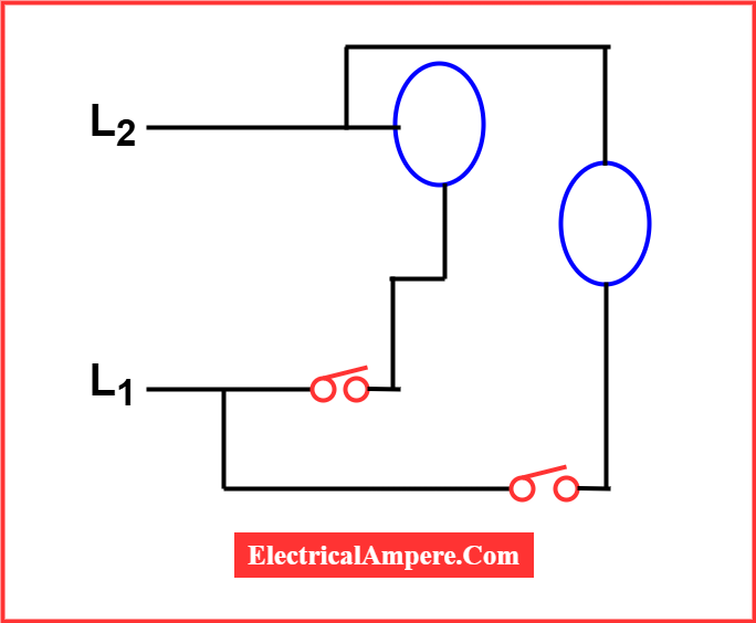
6). Line Diagram or Ladder Diagram

Ladder diagrams are commonly used in industrial settings to represent control logic systems. They are called “ladder diagrams” because their layout resembles the structure of a ladder.
In these diagrams, the left vertical line represents the power rail or voltage source, while the right vertical line signifies the neutral or ground. The horizontal lines, known as “rungs,” represent parallel circuits that form the control logic.
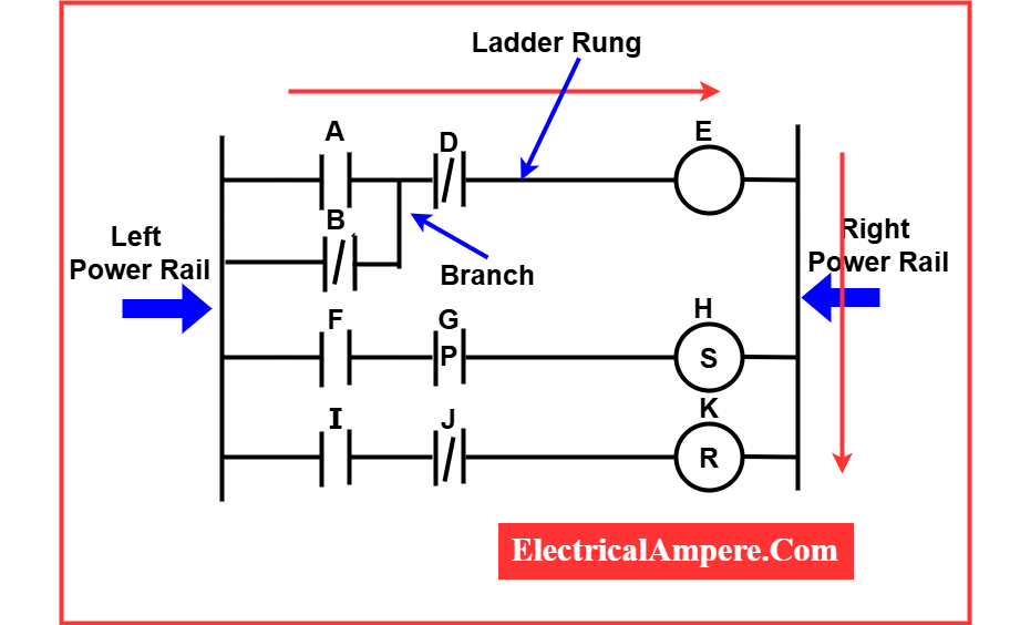
The rungs of a ladder diagram consist of cables and input devices that either allow or prevent current flow to the output devices. When viewed alongside the vertical power rails, these horizontal lines might appear narrow, but they play a crucial role in defining the circuit’s control logic.
The placement of input and output devices on these rungs determines the sequence of operations that either energize or de-energize the outputs. Understanding this sequence is essential for accurate troubleshooting of control systems.
Typically, input devices (such as switches or sensors) are positioned on the left side of each rung, while output devices (like relays, motors, or indicators) are located on the right side.
Ladder diagrams are simple, intuitive, and easy to interpret, making them highly effective for quick troubleshooting and understanding circuit flow in industrial automation systems.
7). Logic Diagram
Logic diagrams are used to represent complex digital circuits and processes through the use of symbols and blocks. Each symbol denotes a specific logic function—such as AND, OR, NOT—while blocks may represent more advanced or composite logic operations.
To simplify understanding, especially for those unfamiliar with internal structures, these blocks are often labeled according to their logic function. Lines connecting the blocks illustrate the input and output signal flow between them.

Unlike other electrical diagrams, a logic diagram does not represent electrical properties like voltage, current, or power. Instead, it focuses solely on the logical operation of the circuit in binary terms—using 1s and 0s.
Logic diagrams are widely used in the design and analysis of digital logic systems, such as processors, memory circuits, and digital controllers.
8). Riser Diagram
A riser diagram is a single-line representation that illustrates the power distribution layout in a multi-storey building. It shows how electrical power flows vertically from the main entry point to various sub-circuits on each floor.
This diagram includes important details such as:
- Conduit sizes
- Wire sizes
- Circuit breaker ratings
- Ratings of switches, plugs, and outlets
- Telecommunication and internet connections
The term “riser” comes from the diagram’s vertical format, which represents how electricity “rises” from floor to floor. While it does not show the exact physical location of the components, it emphasizes the flow and distribution of power throughout the building.

Riser diagrams are one of the essential types of electrical diagrams, especially helpful for understanding how the lighting, heating, and ventilation systems operate in a structure. If any issues or hazards arise, they can be easily identified and resolved by referring to the diagram.
Electrical engineers and professionals rely heavily on riser diagrams to ensure safe and efficient power distribution and to mitigate potential electrical hazards in multi-level buildings.
9). Electrical Floor Plan
An electrical floor plan is a vertical illustration that displays the layout of various electrical appliances in a building—such as lights, switches, and fans. It provides precise details about the placement of each component, including its size and distance from surrounding walls and ceilings.
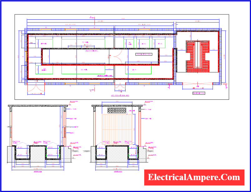
This type of drawing offers a top-down miniature view of each room or area, making it easier to visualize how electrical components are arranged in the actual space.
Electrical floor plans typically include a legend or key that explains the symbols used to represent different electrical devices. These plans are essential for electrical contractors when wiring a newly constructed building or rewiring an existing one. In the case of multi-storey buildings, a separate floor plan is prepared for each level to ensure accurate and safe electrical installations.
10). IC Layout Diagram
The IC layout diagram (also known as the IC mask layout) refers to the interior design of an electrical semiconductor component. An integrated circuit (IC) is composed of multiple layers—such as metal, oxide, and semiconductor materials—each of which plays a critical role in the circuit’s function.
This diagram visually represents the shape, size, and interconnection of these different layers. It essentially outlines the internal architecture of the IC, providing detailed insight into how each layer is arranged and how they interact with one another.

IC layout diagrams are fundamental in the design and fabrication of integrated circuits, serving as blueprints during the manufacturing process to ensure accurate construction of complex semiconductor devices.
Read Next: