Electrical circuits often have more than one power source, such as multiple batteries or generators. Solving such circuits directly can be complex. The Superposition Theorem provides a systematic way to simplify the process by considering one source at a time and then combining the results.
This article explains the superposition theorem definition, its statement, step-by-step method, superposition analysis, examples, applications, and limitations.
What is Superposition Theorem?
The Superposition Theorem is a principle used in linear electrical circuits. It states that the total current or voltage across any component of a network with multiple independent sources is equal to the sum of the currents or voltages produced by each source acting individually.
In other words, instead of solving the entire network at once, you “switch on” one source at a time, calculate its effect, and finally add them together. This method is known as superposition analysis, and it is widely applied in both DC and AC circuits.
Superposition Theorem Definition
The superposition theorem definition can be expressed as:
It is a method in circuit analysis where the total response in a linear electrical circuit containing multiple independent sources is obtained by calculating the effect of each source separately and then adding these effects together.
This makes it clear that the theorem is valid only for linear circuits (resistors, capacitors, inductors). Non-linear devices such as diodes or transistors do not follow this rule.
Statement of Superposition Theorem
The statement of Superposition Theorem is:
In any linear electric circuit with two or more independent sources, the response (voltage or current) across any element is equal to the algebraic sum of the responses produced by each source acting alone, with all other sources replaced by their internal impedances.
How to Apply Superposition Theorem (Step-by-Step Method)
To state and explain Superposition Theorem in practical terms, follow these steps:
- Choose one source at a time
- Replace all other voltage sources with a short circuit.
- Replace all other current sources with an open circuit.
- Solve the reduced circuit
- Find the current or voltage in the required branch due to the active source.
- Repeat for all other sources
- Activate each independent source one by one and calculate its contribution.
- Add the results
- The total current or voltage is the algebraic sum of all contributions.
This process is called superposition analysis, and it is the backbone of superposition in circuits with multiple sources.
Superposition Theorem Example (Step-by-Step Solution)
Let’s take a simple superposition circuit example:

Given
R1=8 Ω, R2=6 Ω, R3=3 Ω
Left source B1=20 V (sets the left top node to 20 V)
Right source B2=10 V (sets the right top node to 10 V)
Bottom rail is ground (0 V). Let the center node be Vx.
Sign conventions:
- IR1: positive from left node → Vx
- IR3: positive from Vx → right node
- IR2: positive from Vx → ground
This superposition example clearly shows how analyzing one source at a time makes the problem much easier.
Step 1 – B1 Active, B2 Replaced by Short

Right node becomes 0 V.
KCL at Vx:
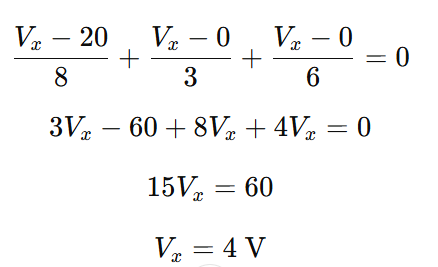
Currents (positive “from Vx” toward each element unless noted):
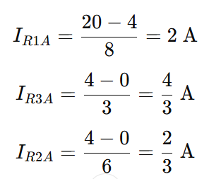
Branch currents:
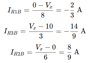
Step 2 – B2 Active, B1 Replaced by Short
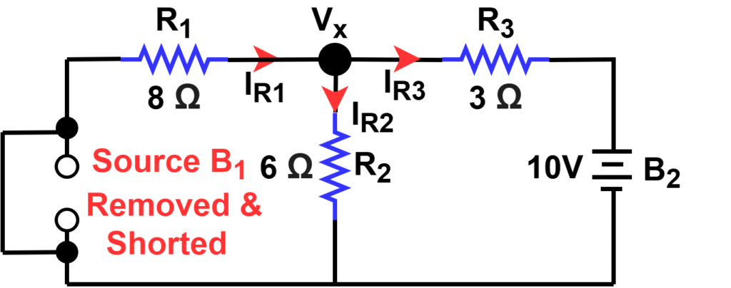
Left node becomes 0 V; right node is 10 V.
KCL at Vx:
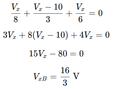
Branch currents:
Step 3 – Superpose the Contributions
Node voltage:

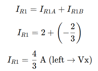
Total branch current IR1
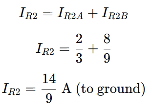
The total branch current IR2
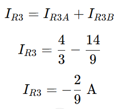
Total branch current IR3
Step 4 – Quick Checks (KCL Verification)
KCL at node:
Incoming Current ( IR1+IR3) =4/3+2/9=14/9 A=Outgoing Current IR2
This superposition example clearly shows how analyzing one source at a time makes the problem much easier.
How to Replace Sources in Superposition Theorem (Voltage & Current Sources)
In the superposition theorem, you analyze one source at a time and replace the others with their internal resistance.
- Short the voltage source → An ideal voltage source has zero internal resistance, so you short it.
- Open the current source → An ideal current source has infinite internal resistance, so you open it.
These steps simplify the circuit and make superposition analysis easier and more accurate.
Superposition Theorem in Circuits (DC and AC)
The superposition principle in circuits is widely applied in:
- DC circuits with multiple voltage sources
- AC circuits with sinusoidal sources of different magnitudes and phases
- Mixed electrical networks with both current and voltage sources
Such superposition electric circuits or superposition electrical circuits are common in power distribution, communication systems, and amplifier design.
Applications of Superposition Theorem
The superposition theorem is widely used in electrical and electronic engineering. Its main applications include:
- Power systems → It helps analyze circuits with multiple voltage and current sources.
- AC and DC circuit analysis → Since both AC and DC equations follow Ohm’s law linearly, you can analyze AC sources and DC sources separately, then combine their effects. This is especially useful when AC signals are superimposed on DC bias.
- Amplifier circuits → In semiconductor amplifiers, AC signals are often mixed with a DC supply. Using superposition, you can study the AC response separately from the DC operating point, making analysis much simpler.
- Mixed electrical networks → The theorem helps understand load behavior when multiple independent sources act simultaneously.
By breaking down the effect of each source, superposition reduces complex circuit analysis into simpler steps and avoids solving difficult simultaneous equations.
Limitations of Superposition Theorem
Although very useful, the superposition theorem has some important limitations:
- It applies only to linear circuits (resistors, capacitors, inductors). Non-linear devices such as diodes, transistors, and varistors do not follow this rule.
- You cannot use it directly to calculate power because power depends on the square of voltage or current. The theorem only works for voltage and current calculations.
- The theorem is not effective for complex networks like unbalanced bridge circuits that cannot be reduced to simple series or parallel combinations.
- It requires all components to be bilateral, meaning they behave the same regardless of current direction.
These limitations show that while the superposition theorem is powerful for analyzing linear networks, it is not suitable for power calculations or circuits containing non-linear elements.
Conclusion
The Superposition Theorem is a powerful method in circuit analysis that breaks down complex networks into simpler problems. By considering one source at a time and then combining the effects, it provides a structured and reliable way to calculate circuit responses.
By mastering this principle, you can easily analyze superposition circuits in both academic and practical applications.
Related Articles: