A series circuit is one of the most basic yet essential types of electrical circuits. Understanding it is crucial for beginners, electronics students, and anyone working with electrical systems.
In this article, we’ll explain what a series circuit is, how to draw a series circuit diagram, calculate resistance in series circuits, analyze voltage distribution, and explore practical applications in everyday life.
What is a Series Circuit?
A series circuit is a type of electric circuit where components are connected one after another in a single path. The current has only one path to flow through all components. This arrangement creates unique characteristics:
- The same current flows through all components.
- The voltage divides among the components based on their individual resistances.
- If any component fails, the entire circuit stops working.
- Series circuits are simple to design, analyze, and construct, making them ideal for learning and basic applications.
Example: Old-style Christmas lights often use a series connection. If one bulb burns out, the entire string goes dark, demonstrating the dependency of the circuit on all components.
How to Draw a Series Circuit Diagram
A series circuit diagram is a graphical representation of components connected in series. Drawing a proper diagram helps visualize the current path and understand voltage distribution.
Steps to Draw a Series Circuit Diagram
- Draw the Voltage Source: Start with a battery or DC supply.
- Connect Components in Series: Place resistors, bulbs, or other loads sequentially in a single path.
- Complete the Circuit: Connect the last component back to the voltage source.
Example- Series Circuit Diagram
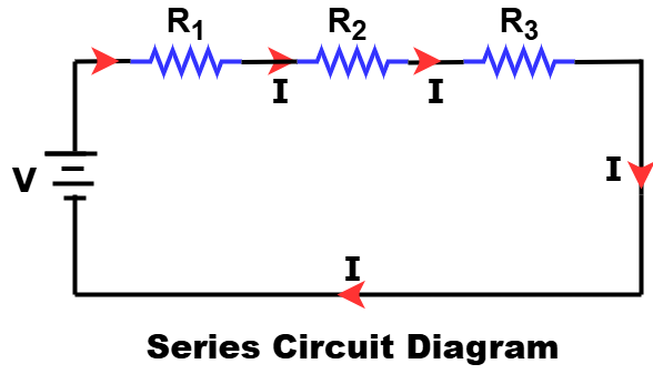
R1,R2,R3represent resistors connected in series.- The same current I flows through all resistors.
- Voltage divides across each resistor depending on its resistance.
Calculating Resistance in a Series Circuit
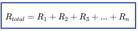
One of the simplest advantages of a series circuit is that calculating total resistance is straightforward. The total resistance is the sum of all individual resistances:
Example:
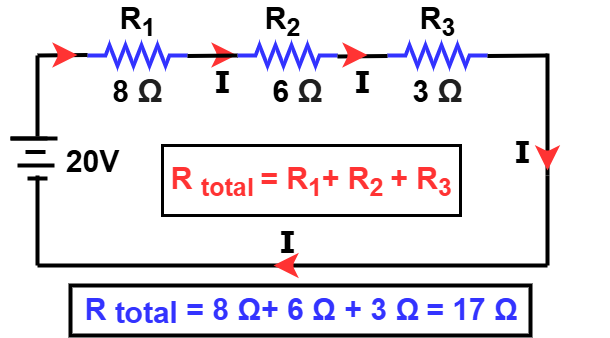
- R1 = 8 Ω, R2 = 6 Ω, R3 = 3 Ω
- Total Resistance:
Rtotal = 8+6+3=17 Ω
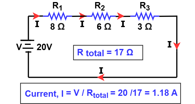
Calculating Current in Series Circuit:
In a series circuit, the same current passes through every component because there is only one path for the current to flow.
Using Ohm’s Law:
I=V / Rtotal
For a 20V battery:
I=20/17=1.18A
This current flows through all components equally, which is a defining feature of series circuits.
Voltage Distribution in Series Circuits
In a series circuit, voltage is not the same across each component. Instead, it divides among components according to their resistance. This principle is often used in voltage divider circuits.
Vn=I × Rn
where,
- Vn= Voltage across the nth resistor
- Rn = Resistance of the nth resistor
Example: With R1 = 8 Ω, R2 = 6 Ω, R3 = 3 Ω and I = 1.18 A:
- V1 = 1.18 × 8 = 9.44 V
- V2 = 1.18 × 6 = 7.08 V
- V3 = 1.18 × 3 = 3.54 V
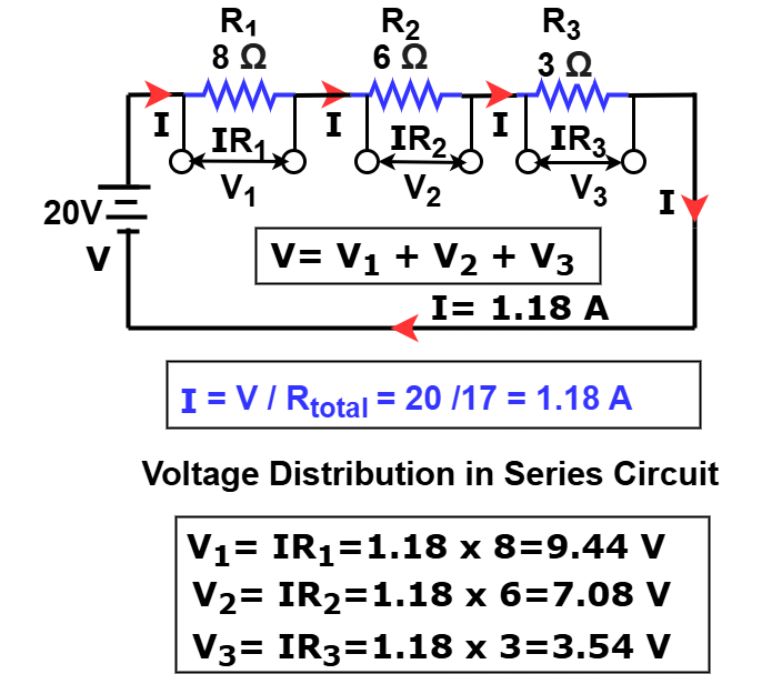
The sum of all voltage drops equals the total supply voltage (20V).
Power Dissipation in Series Circuits
In a series circuit, each resistor dissipates electrical energy as heat. The power dissipated by each resistor depends on the current flowing through it and its resistance.
The formula for power dissipation is:
Where:
- Pn = Power dissipated by the nth resistor (in watts)
- I= Current through the series circuit (same for all resistors)
- Rn = Resistance of the nth resistor
Example:
For a series circuit with I=1.18 A and resistors R1=8 Ω, R2=6 Ω R3=3 Ω, the power dissipation in each resistor is,
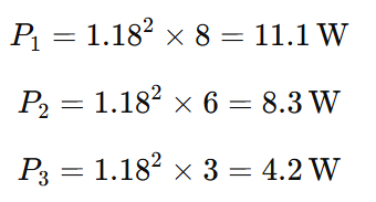
Key Points on Power Dissipation in Series Circuits
- All resistors in series share the same current, so power dissipation is proportional to their resistance.
- Higher resistance resistors dissipate more power.
- Understanding power dissipation is important to ensure resistors are rated correctly and avoid overheating.
Advantages of Series Circuits
Series circuits are simple but useful in many scenarios. The main advantages are:
- Simple Design: Easy to build and analyze, ideal for beginners.
- Fewer Wires Needed: Compared to parallel circuits, series connections use less wiring.
- Good for Learning and Experiments: Ideal for classrooms and electronics labs.
Disadvantages of Series Circuits
Despite their simplicity, series circuits have limitations:
- Single Point of Failure: If one component fails, the whole circuit stops working.
- Voltage Division: Devices may receive less voltage than needed.
- Not Ideal for Independent Operation: Components cannot operate independently because the same current flows through all.
Practical Examples of Series Circuits
Series circuits are commonly used in:
- Simple Bulb Circuit: Multiple bulbs connected sequentially to a battery.
- Voltage Divider Circuit: Resistors in series create specific voltage levels for components.
- Old Christmas Lights: One burned-out bulb affects the entire string.
- Educational Demonstrations: Used in labs to teach current, resistance, and voltage concepts.
Series vs Parallel Circuits (Quick Comparison)
Understanding series and parallel circuits is essential for practical applications. Each type has unique characteristics that make it suitable for specific scenarios.
| Feature | Series Circuit | Parallel Circuit |
| Current | Same through all components | Divides across branches |
| Voltage | Divides across components | Same across each branch |
| Dependency | One failure stops circuit | One failure does not affect others |
| Complexity | Simple | More complex |
| Application | Basic circuits, voltage dividers | Household wiring, high-reliability circuits |
Tips for Drawing and Analyzing Series Circuits
- Label Components Clearly: Helps in analysis and troubleshooting.
- Use Color Coding: Distinguish wires and components in diagrams.
- Verify Values: Use Ohm’s Law to check current and voltage.
- Calculate Total Resistance First: Simplifies overall analysis.
- Use Examples: Hands-on experimentation improves understanding.
Safety Tips for Series Circuits
When building or experimenting with series circuits, keep these precautions in mind:
- Avoid Overloading Resistors: Check the resistor’s power rating to prevent overheating.
- Ensure Correct Power Ratings: Use components rated for the voltage and current in your circuit.
- Use Insulated Wires: Prevent short circuits and accidental shocks by using properly insulated wires.
- Turn Off Power Before Modifying Circuits: Always disconnect the power source when adding or removing components.
Applications of Series Connection
Series circuits are widely used in practical scenarios where the same current must flow through all components. Common applications include:
- Voltage Divider Circuits: Obtain specific voltages from a larger supply.
- Current Limiting in LEDs: Protect LEDs by controlling the current through them.
- String Lights (Christmas Lights): If one bulb goes out, the entire string stops, demonstrating series behavior.
- Fuse + Resistance Combinations: Provide simple protection circuits in electronics.
- Battery-operated Devices: Flashlights and simple gadgets use series connections for uniform current.
- Simple Measuring Instruments: Certain meters use series resistors for voltage measurement.
- Laboratory Experiments and Educational Kits: Ideal for teaching current, resistance, and voltage concepts.
- Low-cost Sequential Circuits: Any application where components need to operate in a specific sequence (like small indicator lights or basic hobby projects).
Summary / Quick Formula Table
| Concept | Formula |
| Total Resistance | Rtotal = R1 + R2 + … + Rn |
| Current | I = V / Rtotal |
| Voltage across nth resistor | Vn = I × Rn |
| Power dissipated | Pn = I² × Rn |
Conclusion
A series circuit is a fundamental building block of electronics. By understanding series circuit diagrams, resistance in series, and voltage distribution, you can effectively design, analyze, and troubleshoot circuits.
Series circuits are perfect for learning, experiments, and simple applications, and they form the foundation for more complex parallel and combination circuits. Mastering series circuits is the first step toward a deeper understanding of electrical and electronic systems.
Related Articles: