Understand the Reciprocity Theorem in electrical engineering, including its statement, formula, diagram, applications, and examples for simplified circuit analysis.
Introduction to Reciprocity Theorem
The reciprocity theorem is a powerful concept in circuit theory and electrical engineering, introduced by physicist Max Theodor Felix von Laue. It is used to analyze linear, bilateral circuits with a single independent source. The theorem confirms the symmetrical response of current and voltage, simplifying circuit analysis for students, engineers, and professionals alike.
What is Reciprocity Theorem?
The reciprocity theorem explains the symmetrical behavior of a linear bilateral network, where voltage and current relationships remain consistent when source and response points are interchanged. It states that if a voltage source placed at one point in the circuit produces a current at another point, then moving the same source to the second point will produce the same current at the first.
This principle helps simplify circuit analysis by showing that the positions of the source and the response (current measurement point) can be interchanged without changing the result.
Reciprocity Theorem Statement
The formal reciprocity theorem statement is:
“In any linear, bilateral network with a single independent voltage source, the current at one branch due to a source placed at another branch will remain the same if their positions are interchanged.”
Explanation of Reciprocity Theorem
The reciprocity theorem applies specifically to a linear bilateral network with a single independent source. It indicates that the position of the voltage source and the measured current branch can be interchanged without altering the current value—as long as the source polarity matches the current direction. This reflects a consistent voltage-current relationship, which simplifies analysis in network theorems.
The reciprocity theorem diagram below illustrates this concept clearly:
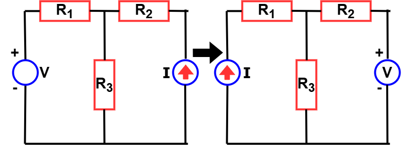
In the circuit, resistors R1, R2, and R3 are connected alongside a voltage source (V) and a current source (I). As seen, the position of the voltage and current sources is interchanged, yet the response in terms of current remains unchanged—confirming the behavior predicted by the reciprocity theorem.
Conditions for Validity
The reciprocity theorem is applicable only under specific conditions. For the theorem to hold, the electrical network must meet the following criteria:
- Linear Network: All components must follow Ohm’s Law, meaning the relationship between voltage and current is directly proportional.
- Bilateral Network: The behavior of circuit elements must be the same in both directions. For instance, a resistor offers the same resistance regardless of current direction.
- Single Independent Source: The network must contain only one independent voltage or current source. Multiple independent sources will invalidate the theorem. (Independent sources provide a fixed voltage or current not influenced by other elements in the circuit.)
- No Non-Linear or Time-Varying Elements: The circuit should not include components like diodes, transistors, or dependent sources, which introduce non-linearity or time-varying behavior.
These conditions ensure the symmetry required for the reciprocity theorem to be valid. When met, this property becomes especially useful in analyzing two-port networks, signal transmission paths, and passive circuit behavior.
Reciprocity Theorem Formula
Though there’s no fixed formula, the concept can be described as:
If
V at A → I at B
then
V at B → I at A
This represents a fundamental voltage-current relationship in a reciprocal circuit: if V₁ at branch A causes I₂ at branch B, then V₁ at branch B causes I₂ at branch A.
Steps for Solving a Network Utilizing Reciprocity Theorem
To apply the reciprocity theorem effectively in a linear bilateral network, follow this methodical approach:
Step 1 – Identify the Network Type
Ensure the circuit is a linear, bilateral network with only one independent voltage or current source. The theorem does not apply to systems with multiple sources or non-linear elements.
Step 2 – Choose the Branches
Select the two branches between which you want to establish reciprocity—i.e., where the source is applied and where the response current is to be observed.
Step 3 – Apply the Source and Calculate Current
Insert the voltage source at the first branch and use any conventional network analysis method (e.g., mesh or nodal analysis) to calculate the resulting current at the second branch.
Step 4 – Swap the Voltage Source
Now, interchange the voltage source to the second branch and measure the current at the original branch.
Step 5 – Compare the Results
Verify whether the currents obtained in both cases are identical. If they are, the reciprocity theorem holds true for that network.
Advantages of Reciprocity Theorem
- Simplifies circuit analysis
- Reduces redundant calculations
- Useful for two-port network analysis
- Verifies linearity and bilateral nature of circuits
- Saves time in mesh and nodal analysis
Reciprocity Theorem Application
The reciprocity theorem is widely applied in:
- Telecommunication networks
- AC and DC circuit analysis
- Measurement systems
- Two-port network analysis
Note: Though the term is also used in nuclear physics and mechanics, this article focuses solely on electrical engineering.
Reciprocity Theorem in Two-Port Network
In two-port network analysis, the reciprocity theorem states that the transfer parameters between the input and output ports remain the same when their positions are interchanged—provided the network is linear and bilateral.
Mathematical Condition:
For impedance parameters (Z-parameters):
Z21 = Z12
For admittance parameters (Y-parameters):
Y21 = Y12
This condition signifies that the voltage-current relationship is unaffected by the direction of excitation. Hence, the input-to-output behavior is identical to the output-to-input behavior, making the system reciprocal.
Example: Consider a passive RC network acting as a two-port system:
- Apply a voltage at Port 1 and measure current at Port 2.
- Swap the voltage source to Port 2 and measure current at Port 1.
If the measured values are the same in both cases, then reciprocity holds.
By ensuring that the transfer impedance from port two to port one is equal to the transfer impedance from port one to port two (that is, Z two one equals Z one two), engineers can confidently design systems that behave symmetrically. This simplifies analysis, reduces the need for repeated testing, and ensures consistent performance in both directions of signal flow.
Reciprocity Theorem Solved Example
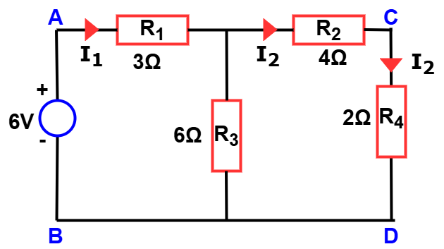
Consider a linear bilateral network consisting of four resistors labeled R₁, R₂, R₃, and R₄, connected in a mesh configuration. A voltage source is applied across terminals A and B, and the resulting current is measured through branch C–D.
First, apply a 6V voltage source across nodes A and B. Measure the resulting current flowing through branch C–D.
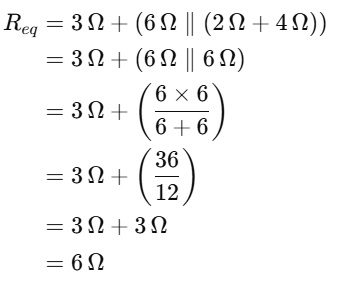
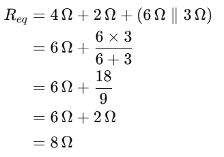
The equivalent resistance(AB)
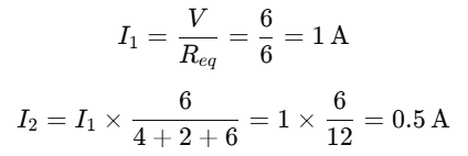
Current through branch CD
Now, switch the voltage source to nodes C and D, and measure the current flowing through branch A–B.

The equivalent resistance(CD)
Current through branch AB
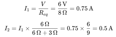
In both cases, the magnitude of the current remains the same at 0.5 Amperes, thereby validating the reciprocity theorem.
Conclusion
Among the fundamental network theorems, the reciprocity theorem stands out as a practical aid for solving real-world circuit problems efficiently. Whether analyzing communication systems, two-port circuits, or signal behavior, it offers both simplicity and reliability.
Next time you’re solving a complex network, let reciprocity be your shortcut to clarity.
FAQs on Reciprocity Theorem
The reciprocity theorem, also known as the reciprocal theorem, states that in a linear, bilateral network with a single independent source, the current at one point due to a voltage at another will remain the same if their positions are swapped.
No, it only applies to linear and bilateral networks with one independent source.
-Not valid for non-linear elements (e.g., diodes, transistors)
-Doesn’t work with dependent sources or multiple independent sources
Yes, especially in signal transmission, instrumentation, and antenna systems.
Yes, as long as the network is linear and bilateral.
Related Articles: