In electrical engineering, the power factor of AC power is defined as the ratio of real power to apparent power. Real power, also known as active power, is the power drawn by the load to perform real work.
One more important term used in AC power systems is apparent power. You may have heard this term before. Apparent power is different from real power. It is the product of root mean square (RMS) voltage and RMS current. In some cases, apparent power is greater than real power. This happens when energy is stored in the load and later returned to the source. This can also occur when a non-linear load changes the shape of the current waveform.
When apparent power is higher than real power, more current flows in the circuit than is needed for real power transfer. If the power factor is less than one, voltage and current are not in phase. This reduces the effective power transfer. A negative power factor occurs when the load generates real power. In this case, the power flows back to the source.
In an electric power system, a load with a low power factor draws more current than a load with a high power factor. This happens even when both loads receive the same amount of useful power. Higher current leads to more energy loss in the distribution system. Also, you need to use larger cross-sectional area wires and large-capacity electrical equipment to supply and handle the extra current flow. Due to these higher costs, electrical utilities charge industrial and commercial customers more with a low power factor. This helps cover the cost of larger equipment and wasted energy.
You can improve the load power factor by Power-factor correction. The total current is reduced by improving the power factor, and as a result, improving the the efficiency of the distribution system connected to it. Linear load, such as an induction motor, has a low power factor and its power factor can be corrected using a passive network like a capacitor. However, non-linear loads like rectifiers distort the current drawn from the system. In such cases, active or passive power factor correction devices are used to reduce distortion and increase the power factor. Power factor correction devices can be placed at a central substation, distributed across the system, or built into power-consuming equipment.
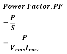
General Expression of Power Factor
The general expression for power factor is given by,
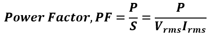
Where:
- P (Real Power) is measured in Watts (W) using an ideal wattmeter.
- Vrms(Root Mean Square Voltage) is measured in Volts (V) using an ideal voltmeter.
- Irms(Root Mean Square Current) is measured in Amperes (A) using an ideal ammeter.
- S (Apparent Power) is the product of Vrms and Irms, measured in Volt-Amperes (VA).
If the load supplies power back to the generator, both real power (P) and power factor will have negative values.
Power Factor Calculation for Periodic Waveform
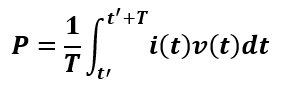
If the voltage and current waveforms are periodic with the same fundamental period, the power factor can be determined using the following formula.
The active power, P can be calculated using the following mathematical formula,
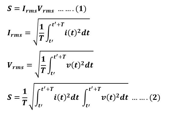
The apparent power, S can be calculated using the follo=ing formula,
The power factor can be calculated by dividing real power by apparent power,
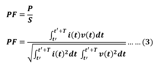
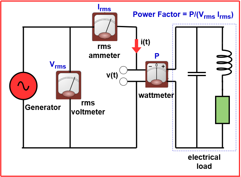
where i(t)) represents the instantaneous current, v(t) represents the instantaneous voltage, t′ is an arbitrary starting time, and T is the period of the waveforms. The following schematic is showing how the power factor is calculated.
If the waveforms are not periodic, the same equations used for periodic cases can still be applied. The physical meters must have the same averaging time. In this case, T represents the averaging time of the meters instead of the waveform period.
Linear circuits
In a linear circuit, the components include resistors, inductors, and capacitors. When a sinusoidal voltage is applied, the current also follows a sinusoidal pattern. A linear load does not change the shape of the input waveform. However, it may shift the timing (phase) between voltage and current due to the presence of inductance or capacitance.
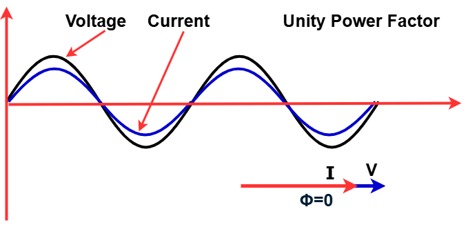
In a purely resistive AC circuit, the voltage and current waveforms are in phase. They change polarity at the same time in each cycle. All the power supplied to the load is completely consumed or dissipated.
When reactive loads like capacitors or inductors are present, energy storage occurs in the load. This causes a phase difference between the current and voltage waveforms. During each AC cycle, some extra energy is temporarily stored in the load’s electric or magnetic fields. This stored energy is then returned to the power grid after a fraction of the cycle.
Electrical circuits with mostly resistive loads, such as incandescent lamps, electric toasters, and ovens, have a power factor close to 1. However, circuits with inductive or capacitive loads, like electric motors, solenoid valves, transformers, and fluorescent lamp ballasts, can have a power factor below 1.
A circuit with a low power factor draws more current to transfer the same amount of real power compared to a circuit with a high power factor. This increased current causes higher losses due to resistive heating in power lines. It also requires larger conductors and higher-rated transformers.
Definition and calculation
AC power has two components:
- Real power (Active power): Denoted as PPP, it is sometimes called average power and is expressed in watts (W).
- Reactive power: Denoted as QQQ, it is usually expressed in reactive volt-amperes (var).
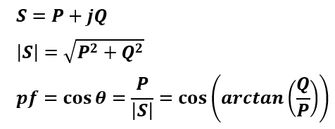
Together, real power and reactive power form complex power (S), which is expressed in volt-amperes (VA). The magnitude of complex power is called apparent power (S), also expressed in volt-amperes (VA).
The volt-ampere (VA) and reactive volt-ampere (var) are non-SI units. They are dimensionally similar to the watt (W) but are used in engineering to specify different power quantities. The SI system does not allow using units alone to define a physical quantity. Additional context is required to clarify what is being measured.
The power factor is the ratio of real power to apparent power. When power is transmitted through a transmission line, it is not purely real power (which performs useful work at the load). Instead, it consists of both real power and reactive power, together known as apparent power. The power factor indicates how much of the apparent power is actually real power that can be used to perform work.
The power factor can also be calculated using the cosine of the angle θ. This angle θ represents the phase difference between the current waveform and the voltage waveform. If the current lags the voltage, the power factor is lagging. If the current leads the voltage, the power factor is leading.
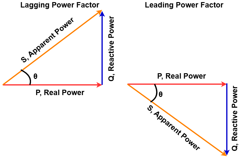
Power triangle
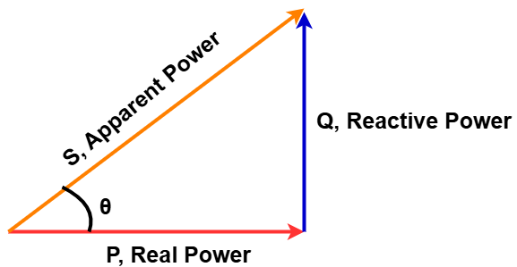
The different components of AC power can be visualized using the power triangle in vector space.
- Real power (P) is represented along the horizontal (real) axis.
- Reactive power (Q) extends along the imaginary axis.
- Complex power (S), which includes both real and reactive power, is the vector sum of these two components.
The relationship between these components follows the Pythagorean theorem:
As the angle θ increases while keeping the total apparent power (S) constant:
- Voltage and current move further out of phase.
- Real power (P) decreases.
- Reactive power (Q) increases.
This means that less of the power is being effectively used for work, and more is being stored and returned in the circuit.
Lagging, leading, and unity power factors
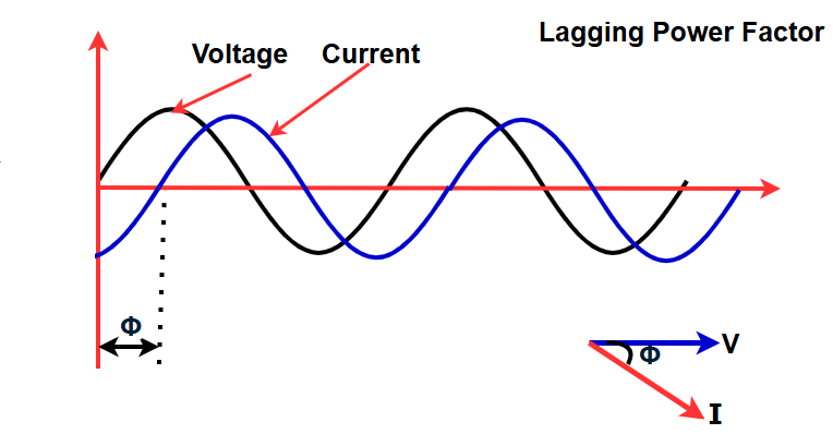
The power factor is called leading when the current waveform is ahead of the voltage waveform. It is called lagging when the current waveform is behind the voltage waveform.
A lagging power factor indicates an inductive load, such as electric motors and transformers. In this case, the load consumes reactive power. The reactive power component (Q) is positive because reactive power flows into the load.
A leading power factor, such as capacitor banks, indicates a capacitive load. Here, the load supplies reactive power. The reactive power component (Q) is negative because reactive power is sent back into the circuit.
If θ is the phase angle between the current and voltage, then the power factor is given by the cosine of the angle:
Power Factor (PF) = cos(θ)
The power factor is a dimensionless number between -1 and 1 since the units are consistent. When the power factor is 0, the energy flow is entirely reactive, meaning the stored energy in the load returns to the source in each cycle. When the power factor is 1, known as the unity power factor, all the energy supplied by the source is consumed by the load.
Power factors are described as leading or lagging to indicate the phase angle direction. Capacitive loads have a leading power factor, where the current leads the voltage. Inductive loads have a lagging power factor, where the current lags the voltage.
If a purely resistive load is connected to a power supply, the current and voltage change polarity in sync. In this case, the power factor is 1, and the electrical energy flows in one direction across the network in each cycle.
Inductive loads, such as induction motors or any wound coil, consume reactive power, causing the current waveform to lag behind the voltage.
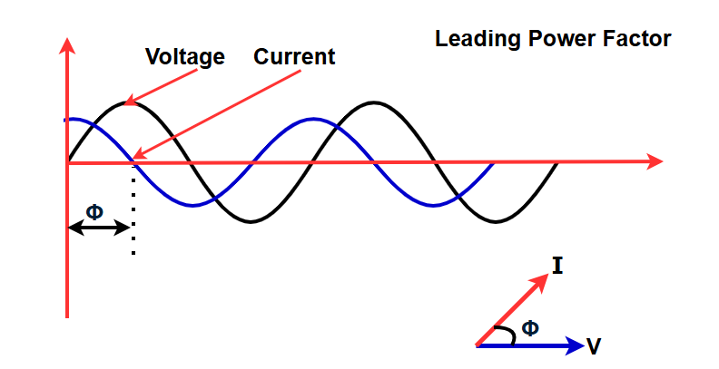
Capacitive loads, such as capacitor banks or buried cables, generate reactive power, causing the current phase to lead the voltage.
Both inductive and capacitive loads store energy during part of the AC cycle in their magnetic or electric fields. This energy is later returned to the source during the rest of the cycle.
For example, to obtain 2 kW of real power, if the power factor is 1 (unity), then 2 kVA of apparent power must be transferred (2 kW ÷ 1 = 2 kVA). At a low power factor, more apparent power is required to deliver the same amount of real power. For instance, at a power factor of 0.3, to get 2 kW of real power, 6.67 kVA of apparent power must be transferred (2 kW ÷ 0.3 = 6.67 kVA). This extra apparent power must be generated and transmitted, leading to higher losses in the power generation and transmission process.
Electrical loads that use alternating current consume both real power and reactive power. The vector sum of these two is called complex power, and its magnitude is known as apparent power. When reactive power is present, the real power becomes less than the apparent power. As a result, the power factor of the electrical load is less than 1.
A negative power factor (ranging from 0 to -1) occurs when active power is sent back to the source. This happens in cases like a building with solar panels, where excess power is fed back into the supply grid.
Power factor correction of linear loads
A high power factor is beneficial in a power delivery system as it reduces losses and improves voltage regulation at the load. Using compensating elements near an electrical load helps lower the apparent power demand on the supply system. Power factor correction is often applied by electric utilities to enhance the stability and efficiency of the network. Customers who are penalized for low power factor may install correction equipment to increase their power factor and reduce costs.
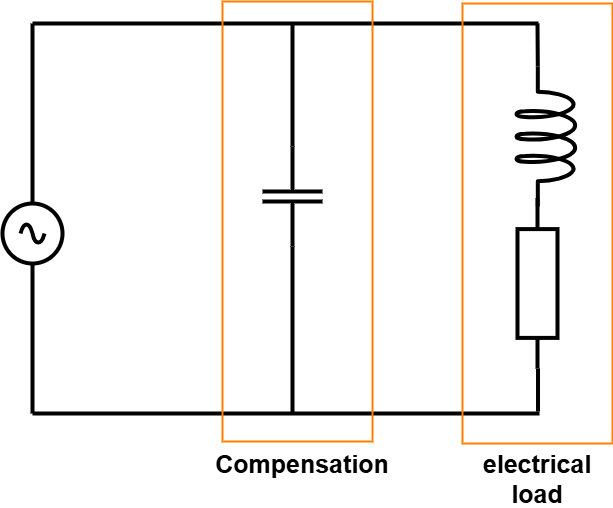
Power factor correction improves the power factor of an AC circuit by bringing it closer to 1. This is done by supplying or absorbing reactive power using capacitors or inductors to counteract the effects of the load. For example, in motor loads, which have an inductive effect, capacitors can be connected locally. These capacitors generate reactive power to meet the demand of the inductive loads, reducing the need for reactive power to flow from the utility generator. In the electricity industry, inductors consume reactive power, while capacitors supply it. However, reactive power itself is just energy moving back and forth during each AC cycle.
Power factor correction devices contain reactive elements that can cause voltage fluctuations and harmonic noise when switched on or off. These elements supply or absorb reactive power even when no corresponding load is present, leading to increased no-load losses. In the worst case, they can interact with the system and each other, creating resonant conditions that cause system instability and severe overvoltage fluctuations. Therefore, engineering analysis is necessary before applying reactive elements to a system.
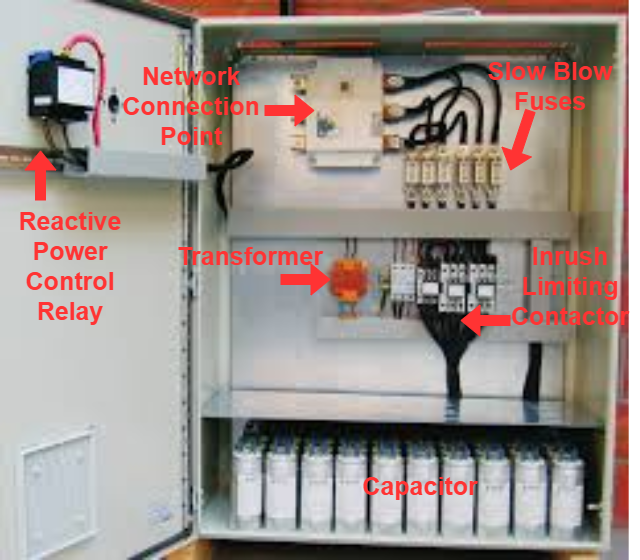
An automatic power factor correction unit contains capacitors that are switched using contactors. A regulator controls these contactors by measuring the power factor of the electrical network. Based on the load and power factor, the power factor controller switches the required capacitor blocks in steps. This ensures that the power factor remains above a selected value.
Instead of using switched capacitors, an unloaded synchronous motor can provide reactive power. The amount of reactive power it supplies depends on its field excitation. This motor is known as a synchronous condenser. It is started and connected to the electrical network. It operates at a leading power factor and supplies reactive power (vars) as needed. This helps in supporting system voltage or maintaining the power factor at a desired level.
The synchronous condenser is installed and operated just like a large electric motor. Its main advantage is that it can easily adjust the amount of power factor correction, acting like a variable capacitor. Unlike capacitors, the reactive power output of a synchronous condenser is directly proportional to voltage, rather than the square of voltage. This helps improve voltage stability in large electrical networks. Synchronous condensers are commonly used in high-voltage direct-current (HVDC) transmission systems and large industrial plants like steel mills.
For power factor correction in high-voltage power systems or large industrial loads, power electronic devices like the Static VAR Compensator (SVC) or STATCOM are widely used. These systems can respond quickly to sudden power factor changes, making them more effective than traditional contactor-switched capacitor banks. Since they are solid-state devices, they also require less maintenance compared to synchronous condensers.
Non-linear loads
Examples of non-linear loads in a power system include rectifiers (used in power supplies) and arc discharge devices like fluorescent lamps, electric welding machines, and arc furnaces. These loads interrupt current flow due to switching actions, causing the current to contain harmonic frequencies that are multiples of the power system frequency. The distortion power factor measures how harmonic distortion in the load current reduces the average power delivered to the load.
Non-sinusoidal components
In linear circuits with only sinusoidal currents and voltages at a single frequency, the power factor depends solely on the phase difference between current and voltage. This is known as the displacement power factor.
Non-linear loads distort the current waveform, changing it from a pure sine wave to a different shape. These loads generate harmonic currents in addition to the fundamental frequency AC current. This is significant in power systems with non-linear loads such as rectifiers, certain electric lighting systems, arc furnaces, welding machines, switched-mode power supplies, and variable speed drives. To prevent harmonic currents from affecting the power supply, filters made of capacitors and inductors are used to block them from entering the system.
To measure real power or reactive power in a system with non-sinusoidal currents, a wattmeter specifically designed for such conditions must be used. Standard wattmeters may not provide accurate readings due to the presence of harmonic currents in non-linear loads.
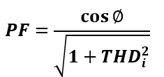
Distortion Power Factor
The distortion power factor is the distortion component associated with the harmonic voltages and currents present in the system.
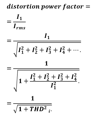
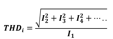
THDi is the total harmonic distortion in the load current.
The distortion power factor can describe individual harmonics by using the corresponding current instead of the total current. This definition of total harmonic distortion assumes that the voltage remains undistorted (purely sinusoidal, without harmonics). This assumption is often accurate for stiff voltage sources, which are not affected by load changes in the distribution network. The total harmonic distortion in typical generators due to current distortion in the network is about 1–2%. While this may have larger effects, it is usually ignored in common practice.
When the distortion power factor is multiplied by the displacement power factor, it gives the overall or true power factor (PF).
Distortion in three-phase networks
In practice, the effect of distortion current on devices in a three-phase distribution network depends more on the magnitude of specific harmonics rather than the total harmonic distortion.
For example, triplen harmonics (3rd, 9th, 15th, etc.) stay in-phase when measured line-to-line.
- In a delta-wye transformer, these harmonics cause circulating currents in the delta windings, leading to higher resistive heating.
- In a wye-configured transformer, triplen harmonics do not create circulating currents but cause a non-zero current in the neutral wire. This can overload the neutral wire and lead to errors in kilowatt-hour metering and billing.
Harmonics in a transformer also increase eddy currents in its magnetic core. Since eddy current losses rise with the square of the frequency, they reduce efficiency, generate excess heat, and shorten the transformer’s lifespan.
Negative-sequence harmonics (5th, 11th, 17th, etc.) are 120 degrees out of phase, similar to the fundamental frequency but in the reverse order. In generators and motors, these harmonics create magnetic fields that oppose the shaft’s rotation. This can lead to mechanical vibrations, which may cause damage over time.
Power factor correction (PFC) in non-linear loads
Passive PFC
The easiest way to control harmonic current is by using a filter that allows only the line frequency (50 or 60 Hz) to pass through. This filter is made of capacitors or inductors and helps a non-linear device behave more like a linear load. An example of a passive power factor correction (PFC) method is the valley-fill circuit.
A drawback of passive PFC is that it needs larger inductors or capacitors compared to an active PFC circuit. Additionally, in practice, passive PFC is often less effective at improving the power factor.
Active PFC
Active PFC uses power electronics to modify the current waveform drawn by a load, improving the power factor. Common types of active PFC include buck, boost, buck-boost, and synchronous condenser circuits. It can be designed as a single-stage or multi-stage system.
In a switched-mode power supply, a boost converter is placed between the bridge rectifier and the main input capacitors. The boost converter keeps a constant output voltage while ensuring the input current stays in phase with the line voltage and at the same frequency. Another switched-mode converter inside the power supply then converts this DC bus voltage into the required output voltage. This method needs extra semiconductor switches and control electronics but allows for smaller and cheaper passive components. It is widely used in practice.
For a three-phase switched-mode power supply (SMPS), the Vienna rectifier can be used to significantly improve the power factor.
- SMPS with passive PFC achieves a power factor of about 0.7–0.75.
- SMPS with active PFC can reach a power factor of up to 0.99.
- SMPS without PFC has a much lower power factor, around 0.55–0.65.
Many active PFC power supplies have a wide input voltage range and can operate on 100V (Japan) to 240V (Europe) AC power. This feature is especially useful in laptop power supplies.
Dynamic PFC
Dynamic Power Factor Correction (DPFC), also called real-time power factor correction, helps stabilize electrical systems during rapid load changes, such as in large manufacturing sites. Standard power factor correction may lead to over or under-correction in such cases, but DPFC adjusts quickly to maintain stability. It uses semiconductor switches, typically thyristors, to rapidly connect or disconnect capacitors or inductors, improving the power factor as needed.
Importance in distribution systems
When the power factor is below 1.0, utilities must generate more power than needed for actual work (real power in watts). This increases generation and transmission costs. For example, if the power factor is 0.7, the apparent power becomes 1.4 times the real power used by the load.
- The line current in the circuit also increases by 1.4 times compared to a 1.0 power factor.
- Since power losses are proportional to the square of the current, they would double in this case.
- Alternatively, system components such as generators, conductors, transformers, and switchgear must be larger and more expensive to handle the extra current.
When the power factor is close to unity, the same transformer (with a fixed kVA rating) can deliver more load current efficiently.
Utilities usually charge extra fees to commercial customers if their power factor falls below a certain limit, typically between 0.9 and 0.95. Engineers focus on power factor because it directly affects the efficiency of power transmission. A higher power factor reduces energy losses and improves system performance.
With rising energy costs and the need for efficient power delivery, active PFC is now more common in consumer electronics. Current Energy Star guidelines for computers require a power factor of ≥ 0.9 at 100% of the rated output in the PC’s power supply. A white paper by Intel and the U.S. Environmental Protection Agency states that PCs with internal power supplies must use active power factor correction to meet the ENERGY STAR 5.0 requirements.
In Europe, the EN 61000-3-2 standard requires power factor correction in consumer products. Households and other small customers are usually not charged for reactive power, so power factor meters are not installed for them.
Measurement techniques
In a single-phase circuit or a balanced three-phase circuit, the power factor can be measured using the wattmeter-ammeter-voltmeter method. This is done by dividing the power (in watts) by the product of the measured voltage and current. For a balanced polyphase circuit, the power factor is the same for all phases. However, in an unbalanced polyphase circuit, the power factor is not uniquely defined.
A direct reading power factor meter can be made using a moving coil meter of the electrodynamic type. It has two perpendicular coils, A and B, mounted on the moving part of the instrument.
- The instrument’s magnetic field is energized by the circuit current.
- Coil A is connected through a resistor, while Coil B is connected through an inductor.
- The inductor causes a time delay in Coil B’s current compared to Coil A.
How it Works:
- At unity power factor (1.0):
- The current in Coil A is in phase with the circuit current.
- Coil A provides maximum torque, moving the meter pointer to 1.0.
- At zero power factor (0.0):
- The current in Coil B is in phase with the circuit current.
- Coil B provides torque, moving the pointer to 0.0.
- At intermediate power factors:
- The torques from both coils combine, and the pointer moves to a position between 0 and 1.
The polarized-vane type power factor meter is another electromechanical instrument used for measuring power factor. It operates by utilizing a stationary field coil that generates a rotating magnetic field, similar to a polyphase motor. The field coils are connected either directly to polyphase voltage sources in three-phase systems or to a phase-shifting reactor for single-phase applications. A second stationary coil, positioned perpendicular to the voltage coils, carries a current proportional to one phase of the circuit. The moving system consists of two vanes that are magnetized by the current coil. These vanes adjust to a physical angle that corresponds to the electrical angle between the voltage and current sources. This instrument is capable of measuring currents in both directions, providing a four-quadrant display of power factor or phase angle, making it useful in various power measurement applications.
Digital instruments are available that can directly measure the time delay between voltage and current waveforms. Low-cost versions of these instruments typically measure the peak of the waveforms, while more advanced models focus on the peak of the fundamental harmonic, providing a more precise phase angle measurement, especially for distorted waveforms. However, calculating power factor based on voltage and current phases is only accurate when both waveforms are purely sinusoidal.
Power Quality Analyzers, also known as Power Analyzers, digitally record voltage and current waveforms for one-phase or three-phase systems. They accurately calculate true power (watts), apparent power (VA), power factor, AC and DC voltage and current, frequency, and harmonic measurements based on IEC61000-3-2/3-12 standards. These analyzers also measure flicker (IEC61000-3-3/3-11), total harmonic distortion, and the phase and amplitude of individual voltage or current harmonics. In delta applications without a neutral line, they can determine individual phase voltages.