Learn the definition of phase and phase difference in electrical engineering. Understand how they influence AC circuits, waveforms, and power systems with clear explanations and examples.
Definition of Phase in Electrical:
The phase of an alternating quantity refers to the fractional part of a complete cycle that the quantity has progressed from a chosen reference point. The electrical phase indicates the position of the waveform relative to time or another waveform.
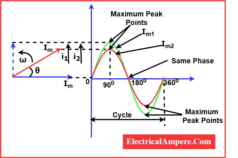
When two alternating quantities have the same frequency and reach their maximum, minimum, and zero values at the same instant, they are said to be in phase. This condition reflects perfect synchrony between the waveforms. For instance, in the case of two AC currents, if both phases of AC current—say Im₁ and Im₂—attain their peaks and cross zero simultaneously, their phase difference is zero, meaning the two waveforms are in phase.
This concept is crucial in understanding alternating current phase, especially in systems where multiple electrical phases are involved, such as three-phase power systems.
Phase Difference Definition in Electrical:
The phase difference refers to the angular displacement between the peaks (or any identical points) of two alternating quantities (like voltage or current) that share the same frequency. In simple terms, what is phase difference? It’s the angle (measured in degrees or radians) by which one waveform leads or lags behind another.
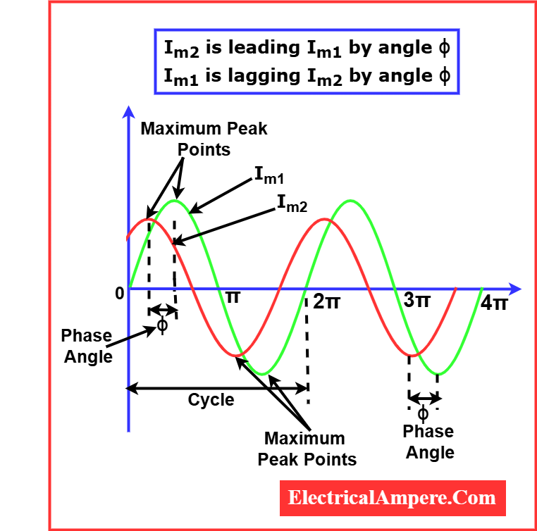
When one alternating current, say Im₁, reaches its positive maximum before another current Im₂, Im₁ is called the leading quantity, and Im₂ is called the lagging quantity. Thus, Im₁ leads and Im₂ lags. This concept is critical in AC systems where the phase of alternating current determines power flow and system behavior.
Cycle Definition in Electrical Phases:
A cycle is the complete set of values (both positive and negative) of an alternating quantity within 360° of electrical phase angle. When an AC signal completes this, it is said to have completed one full cycle.
In situations where two alternating currents have the same frequency but reach their zero value at different instants, they exhibit a phase difference. The angle between these zero-crossing points is known as the angle of phase difference.
Vector Representation of Phase Difference:

Consider two alternating currents with magnitudes Im₁ and Im₂, rotating vectorially at the same angular velocity (ω) in radians per second. Although both rotate at the same speed, they attain zero values at different times. Hence, there is a phase difference denoted by the angle φ (phi). This angle quantifies how much one wave is leading or lagging with respect to the other.
Mathematical Representation of Phase Difference in Electrical
In electrical engineering, the phase difference between two alternating quantities (usually voltage and current) is mathematically represented using sinusoidal functions. Here’s how it’s expressed:
Let two alternating quantities (e.g., voltages or currents) be:
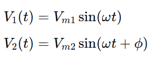
Where:
- Vm1,Vm2= Maximum (peak) values
- ω = Angular frequency in radians/second
- t= Time in seconds
- ϕ= Phase difference in radians
Interpretation of Phase Angle ϕ
- If ϕ>0: V2 leads V1 by ϕ radians
- If ϕ<0: V2 lags V1 by ϕ radians
- If ϕ=0: Both waveforms are in phase
Example:
Let’s say we have:
An alternating voltage given by:
V(t)=230sin(ωt)
And an alternating current given by:
I(t)=10sin(ωt−6π)
Given Values:
- Vm=230 V (voltage amplitude)
- Im=10 A (current amplitude)
- ω= Angular frequency
- ϕ=−6π radians (phase difference)
Interpretation:
- Since ϕ=−π6, the current lags the voltage by π6 radians or 30 degrees.
- This indicates the presence of inductive load, which is typical in motors or transformers.
- The power factor can be calculated as: Power Factor=cos(ϕ)=cos(π6)=cos(30∘)=0.866 ➤ So the power factor is 0.866 lagging.
Phase Difference and Power Factor Relationship
When voltage and current are in phase ( ϕ=0∘ ):
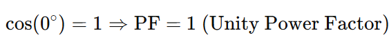
This means all the power is real power, with no reactive component. Found in purely resistive circuits.
When current lags voltage ( ϕ>0∘ ):
This is typical in inductive circuits (like motors, transformers).
When current leads voltage ( ϕ<0∘):
This happens in capacitive circuits.
Variation of Waveforms and Phase Difference in Electrical Systems
In alternating current (AC) systems, waveform variation plays a critical role in understanding how electrical quantities like voltage and current interact over time. These variations are primarily observed through the phase relationship between waveforms. This relationship can be categorized into the following three conditions:
- In-Phase
- Out-of-Phase (Leading or Lagging)
- Phase Difference (Φ)
1. In-Phase Waveforms
Definition:
Two waveforms are said to be in phase when they have the same frequency and phase, meaning they reach their corresponding zero, maximum, and minimum values at exactly the same time.
Characteristics:
- Phase difference (Φ) = 0°
- Waveforms rise and fall together
- They can have different amplitudes but must have the same timing
Example:
Sine waves with equal frequency but different peak values (amplitudes) and identical timing are considered in-phase. The number of cycles completed aligns perfectly (e.g., 3, 4, 5 full wavelengths).
2. Out-of-Phase Waveforms
Definition:
When two sinusoidal waveforms have the same frequency but differ in phase, they are said to be out of phase. This means their zero crossings, peak, and trough points occur at different instants in time. The angular separation between them is referred to as the phase difference (Φ).
The phase difference is measured in degrees (°) or radians and defines how much one waveform leads or lags behind another.
a) Leading Phase
In a leading phase scenario, one waveform reaches its maximum value before the other. It is said to lead the second waveform.
Mathematical Representation:
- Voltage:
V(t) = Vm × sin(ωt) - Current:
i(t) = Im × sin(ωt – Φ)
Here, Φ is the phase angle by which the current leads the voltage.
b) Lagging Phase
In a lagging phase scenario, one waveform reaches its maximum value after the other. It is said to lag behind the first waveform.
Mathematical Representation:
- Voltage:
V(t) = Vm × sin(ωt) - Current:
i(t) = Im × sin(ωt + Φ)
In this case, Φ represents the phase angle by which the current lags behind the voltage.
3. Positive and Negative Phase Difference
- A positive phase difference (Φ > 0) implies the waveform is leading.
- A negative phase difference (Φ < 0) implies the waveform is lagging.
- A zero phase difference (Φ = 0) indicates the waveforms are in phase.
Summary of Waveform Phase Relationships
| Condition | Frequency | Phase Difference (Φ) | Resulting Behavior |
|---|---|---|---|
| In-Phase | Same | Φ = 0° | Waveforms rise/fall together |
| Out-of-Phase | Same | Φ ≠ 0° | One waveform leads/lags |
| Leading Phase | Same | Φ > 0 | One waveform is ahead |
| Lagging Phase | Same | Φ < 0 | One waveform is behind |
Importance of Phase and Phase Difference in AC Systems:
Understanding what is a phase difference and what is phase is essential in electrical engineering and alternating current phase systems. It affects the power factor, the efficiency of power transmission, and synchronization of AC machines. A poor understanding of the define phase physics concept can lead to power losses and inefficiencies.
Conclusion:
The phase defines the position of a waveform relative to a reference point in time, while the phase difference represents the angular displacement between two waveforms of the same frequency.
In practical electrical and electronic applications, phase difference plays a vital role in determining the power factor, system efficiency, and overall performance. When voltage and current are in phase, power transfer is maximum; when they are out of phase, energy losses increase due to reactive power.
Thus, mastering the concepts of phase, phase difference, and their implications is essential for engineers and technicians working with alternating current (AC) systems, signal analysis, and power distribution.
FAQs on Phase and Phase Difference
1. What is meant by “phase” in electrical systems?
Answer:
In electrical systems, phase refers to the position of a point in time on a waveform cycle. It is typically expressed in degrees or radians and helps determine how waveforms align with one another.
2. What is phase difference?
Answer:
Phase difference is the angular displacement between two waveforms of the same frequency. It shows how much one waveform is leading or lagging behind another, measured in degrees (°) or radians.
3. What does it mean when two waveforms are “in phase”?
Answer:
Two waveforms are in phase when they reach their maximum, zero, and minimum values at the same time. Their phase difference is zero.
4. What does “out of phase” mean?
Answer:
Out of phase means two waveforms of the same frequency do not reach their corresponding values (e.g., peak or zero) at the same time. They have a non-zero phase difference.
5. What is a leading phase?
Answer:
In a leading phase, one waveform reaches its maximum or zero value before the other. This waveform is said to lead, and the phase difference is positive (Φ > 0).
6. What is a lagging phase?
Answer:
In a lagging phase, one waveform reaches its maximum or zero value after the other. This waveform is said to lag, and the phase difference is negative (Φ < 0).
7. How is phase difference represented mathematically?
Answer:
For sinusoidal waveforms:
- Voltage: 𝑉(t) = 𝑉ₘ × sin(ωt)
- Current: 𝑖(t) = 𝐼ₘ × sin(ωt ± Φ)
Where Φ is the phase difference.
8. How does phase difference affect power factor?
Answer:
Phase difference between voltage and current directly impacts power factor. A smaller phase difference means a higher power factor (more real power), while a larger phase difference results in a lower power factor (more reactive power).
9. Can two waveforms have different amplitudes and still be in phase?
Answer:
Yes, waveforms can have different amplitudes and still be in phase as long as their frequency and phase angle are identical.
10. What is the practical significance of phase difference?
Answer:
Phase difference is crucial in AC power systems. It affects energy efficiency, synchronization of generators, motor performance, and is vital in communication systems and signal processing.
Read Next: