Electricity powers everything around us, from mobile chargers to industrial machines. To understand how it flows in circuits, we start with a fundamental principle known as Ohm’s Law. This law explains the relationship between voltage (V), current (I), and resistance (R) in a conductor.
In this article, we’ll cover the Ohm’s Law statement, formula, derivation, experiment circuit, solved examples, applications, and limitations with simple explanations for better clarity.
What is Ohm’s Law?
Ohm’s Law, discovered by Georg Simon Ohm in 1827, describes how electricity behaves in conductors. It explains the link between voltage, current, and resistance in a simple mathematical way.
In simple words:
- Higher voltage → More current (if resistance is constant).
- Higher resistance → Less current (for the same voltage).
Ohm’s Law Statement
The current through a conductor between two points is directly proportional to the potential difference across those points, provided the temperature remains constant.
Ohm’s Law Formula
The mathematical form is: V=I×R
Where:
- V = Voltage (Volts)
- I = Current (Amperes)
- R = Resistance (Ohms, Ω)
Rearranged:
- I = V/R
- R = V/I
Ohm’s Law Triangle (Quick Memory Aid)
Ohm’s Law Triangle is a quick visual tool to remember the relationship between Voltage (V), Current (I), and Resistance (R). Cover any one quantity in the triangle, and the formula for the other two is revealed instantly.
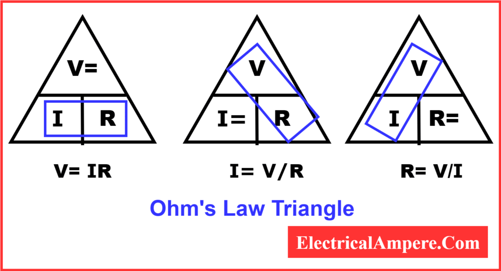
The followings are the ohms law triangle formulas.
- V → I×R
- I → V/R
- R → V/I
This triangle is a quick trick students use to avoid confusion during calculations.
Derivation of Ohm’s Law
From the proportionality relation:
I ∝ V
At constant temperature, this becomes:
I=V/R
Here, R is resistance. Rearranging gives:
V=I×R
Graphical Representation of Ohm’s Law
If we plot voltage (V) on the X-axis and current (I) on the Y-axis for an ohmic conductor:
- The graph is a straight line.
- The slope = 1/R (conductance).
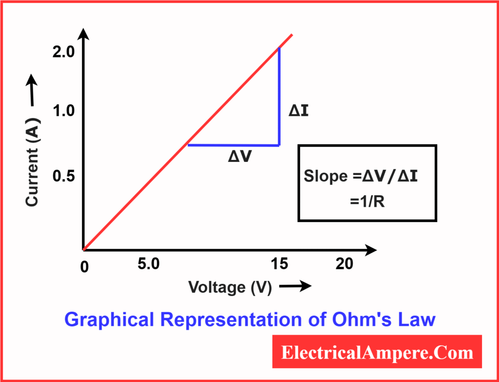
This shows that current increases linearly with voltage.
The equation of a straight line is:
y=mx+c
Here,
- y = dependent variable
- x = independent variable
- m = slope of the line
- c= intercept on the y-axis
In the above VI graph of voltage and current,
y=I, x=V, c=0 and m=1/R
Putting these value in the staright line equation,
y=mx+c
I=1/R .V+0
I= V/R
This is the Ohm’s Law equation.
Ohm’s Law in Terms of Conductance
Since conductance G is defined as the reciprocal of resistance (G=1/R) the equation can also be written as:
I=V/R = G⋅V
Ohm’s Law Experiment Circuit
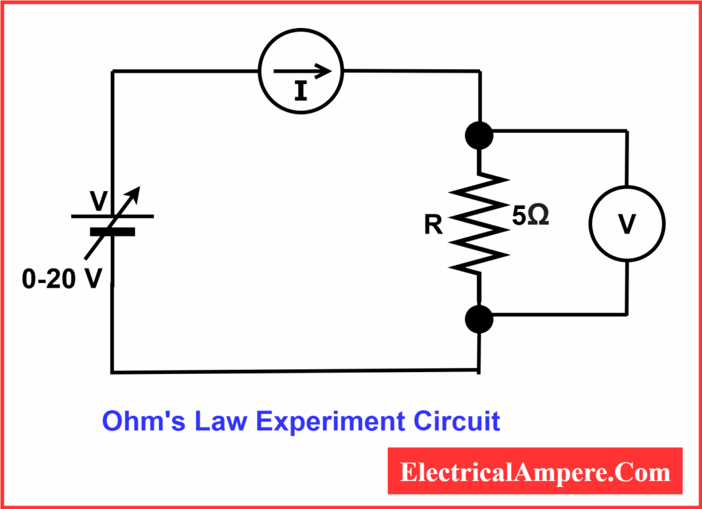
Steps to Verify Ohm’s Law
- Set up the circuit
- Connect a resistor in series with an ammeter and a variable power supply.
- Connect a voltmeter across the resistor to measure the voltage drop.
- Switch on the power supply
- Start with a low voltage to avoid damaging the resistor.
- Record readings
- Adjust the voltage gradually (e.g., 2V, 4V, 8V, 12V, 16V, 20V).
- For each voltage, note the corresponding current from the ammeter.
- Tabulate the results
- Create a table with columns for Voltage (V), Resistance (Ω), and Current (I = V/R).
- Keep resistance constant throughout the experiment.
- Plot the graph
- Draw a graph with Voltage (V) on the X-axis and Current (I) on the Y-axis.
- For an ohmic resistor, the graph should be a straight line, confirming Ohm’s Law.
- Analyze the results
- Observe that current increases proportionally with voltage.
- Verify that the slope of the line equals 1/R, the conductance of the resistor.
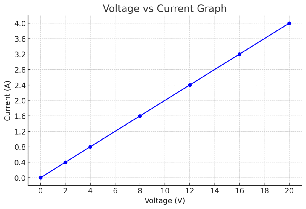
Ohm’s Law Worksheet
| Voltage (V) | Resistance (Ω) | Current (I = V/R) (A) |
| 0 | 5 | 0 |
| 2 | 5 | 0.4 |
| 4 | 5 | 0.8 |
| 8 | 5 | 1.6 |
| 12 | 5 | 2.4 |
| 16 | 5 | 3.2 |
| 20 | 5 | 4.0 |
From the observations, it is clear that the current flowing through the resistor is directly proportional to the applied voltage across it, provided the resistance remains constant.
If we plot a graph of Current (I) versus Voltage (V), the graph is a straight line, which validates Ohm’s Law.
Ohm’s Law Example Problems
To understand V=IR relationship, let us solve some ohm’s law numericals with solutions step by step.
Example 1: Finding Current
A 12V battery is connected across a 6Ω resistor. Find the current.
I=VR=12/6=2A
Current = 2 Amperes
Example 2: Finding Resistance
A conductor carries 5A when a 20V supply is applied. Find resistance.
R=V/I=20/5=4Ω
Resistance = 4 Ohms
Example 3: Finding Voltage
A 10Ω resistor carries 3A of current. Find voltage.
V=I×R=3×10=30V
Voltage = 30 Volts
Example 4: Bulb Problem
A bulb has a resistance of 60Ω. If 0.5A flows, find supply voltage.
V=I×R=0.5×60=30V
Voltage = 30 Volts
These solved examples show how this Law of V = IR can be applied to calculate voltage, current, or resistance in simple circuits.
Applications of Ohm’s Law
The Law of V = IR is widely used in:
- Designing and analyzing electrical circuits.
- Calculating current, resistance, or voltage in a circuit.
- Selecting fuses and circuit breaker ratings.
- Checking safe operating conditions of appliances.
- Power calculations:
- P=V×I
- P=I2R
- P=V2 / R
Limitations of Ohm’s Law
- Valid only for ohmic materials (like metals).
- Not applicable if temperature changes significantly-When the temperature of a conductor rises, its resistance changes depending on the material’s temperature coefficient. Since current is defined by I=V/R, any increase in resistance due to heating will cause the current to vary. In such situations, the ohms law is not strictly valid.
- Fails for non-linear devices such as diodes, transistors, and semiconductors. Ohm’s Law assumes a constant resistance—i.e., a straight-line (linear) relationship between voltage and current. Non-linear devices do not obey this: their I–V curves are curved, so the ratio V/I changes with operating point and the resistance does not remain constent.
Key Takeaways
- Formula: V=I×R
- Graph: Straight line for ohmic conductors
- Uses: Circuit design, fault analysis, power calculation
- Limitation: Not valid for non-linear devices or variable temperature
Conclusion
Ohm’s Law is the foundation of electrical engineering and physics. It provides a simple relationship between voltage, current, and resistance, making it possible to analyze and design electrical systems with ease. By practicing solved examples and applying this law in real scenarios, one can master the basics of electricity and circuit behavior.
Related Articles: