Efficient power delivery is a cornerstone of electrical engineering. Whether you are designing circuits, working with amplifiers, or optimizing energy systems, understanding how to transfer the maximum power from a source to a load is essential. This is where the Maximum Power Transfer Theorem comes into play.
In this article, we’ll explain the theorem in simple terms, derive the essential formulas, and explore its practical applications in everyday electrical and electronic systems.
What is the Maximum Power Transfer Theorem?
The Maximum Power Transfer Theorem, also called the power transfer theorem, is a principle in electrical circuits. It explains how to deliver the greatest amount of power from a source to a load.
In simple terms:
- For DC circuits, maximum power is transferred when the load resistance (RL) equals the internal resistance of the source (Rs).
- For AC circuits, maximum power transfer occurs when the load impedance (ZL) equals the complex conjugate of the source impedance (Zs).
This condition ensures the circuit is tuned for maximum energy delivery. If the load is much higher or lower than the source resistance/impedance, power transfer drops.
Maximum Power Transfer Theorem Statement
The formal statement of the theorem is:
“In a linear electrical network, maximum power is transferred to the load when the load resistance equals the internal resistance of the source, or when the load impedance equals the complex conjugate of the source impedance in AC circuits.”
Why Maximum Power Transfer is Important
Understanding the maximum power theorem formula is crucial for several reasons:
- Circuit Optimization: Ensures that electrical devices and circuits operate efficiently.
- Communication Systems: In antennas and transmission lines, matching impedances ensures minimal signal loss.
- Audio Electronics: Amplifiers deliver the best performance when speaker impedance matches the amplifier’s output resistance.
- Power Systems: Transformers and generators are more effective when loads are correctly matched.
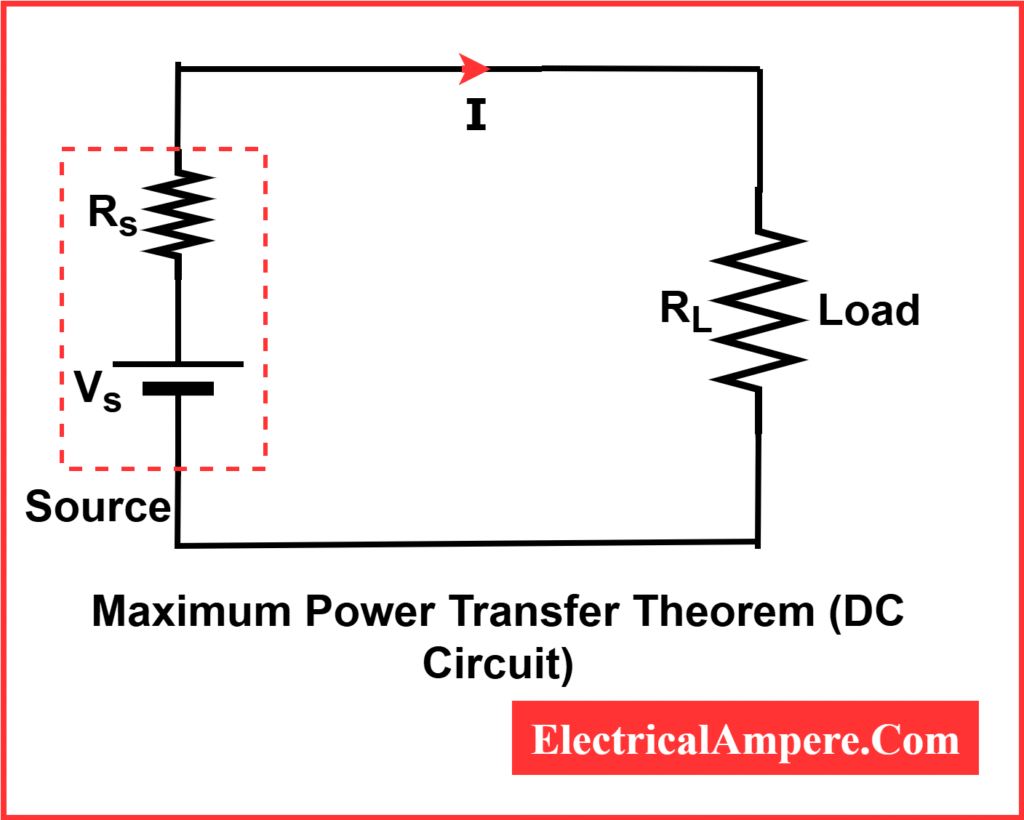
Maximum Power Transfer Formula (DC Circuits)
Let’s look at a simple DC circuit:
- Source voltage: Vs
- Internal resistance of source: Rs
- Load resistance: RL
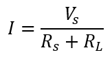
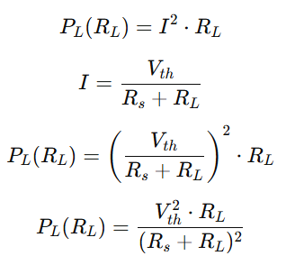
The current in DC circuit.
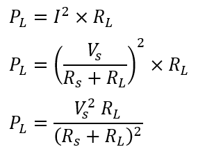
The power delivered to the load is:
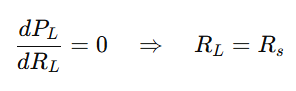
To achieve maximum power: RL=Rs
Substitute RL=Rs into the Power delivered to the load formula:
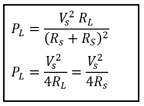
This is the Maximum Power Transfer Formula, also referred to as:
- Maximum power transfer theorem formula
- Maximum power theorem formula
- Maximum power formula
- Formula for maximum power transfer theorem
Maximum Power Transfer Formula (AC Circuits)
For AC circuits, the resistance is replaced by impedance:
- Source impedance: Zs=Rs+jXs
- Load impedance: ZL=RL+jXL
Maximum power is delivered when:
ZL = Zs∗=Rs−jXs
Here, the load impedance must be the complex conjugate of the source impedance to achieve maximum power transfer.
Step-by-Step Guide to Using Maximum Power Transfer Formula
- Identify source voltage and internal resistance: Vs and Rs.
- Determine the load resistance: Set RL=Rs for DC circuits.
- Apply the formula:
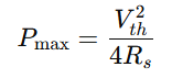
Pmax=Vs2 / 4Rs - For AC circuits: Match load impedance to the complex conjugate of source impedance: ZL=Zs∗
- Calculate delivered power: Use P=I2⋅RL
Maximum Power Transfer Theorem Proof
Here’s a clear, step-by-step proof of the Maximum Power Transfer Theorem for both DC and AC circuits.
1) DC Circuit Proof (Using Calculus)
Consider a Thevenin equivalent seen by the load:
- Thevenin voltage: Vth
- Source (Thevenin) resistance: Rs>0
- Load resistance: RL≥0
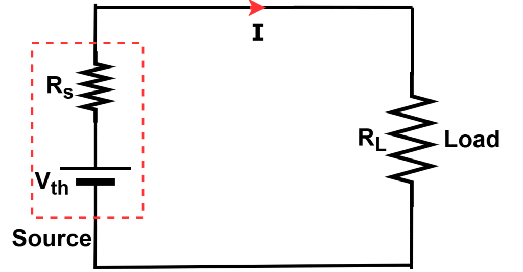
Power in the load:
Differentiate PL with respect to RL
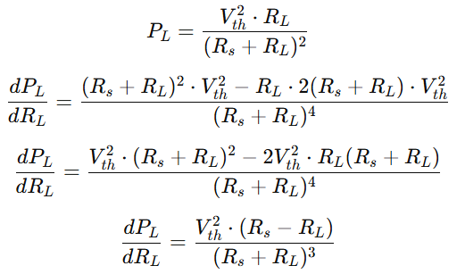
Set derivative to zero for maximum power:
2) AC Circuit Proof (Conjugate Match)
Let the Thevenin equivalent as seen by the load be:
- Vth (phasor), Zs=Rs+jXs with Rs>0
- Load ZL=RL+jXL with RL≥0
Average power absorbed by the load:
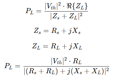
Step 1 (cancel reactance): Choose XL=−Xs so the denominator is smallest (purely real sum).
Now
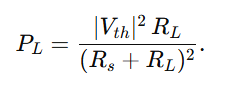
Step 2 (same as DC result): Differentiate as before ⇒ RL=Rs
Thus ZL=RL+jXL=Rs−jXs=Zs∗ (the complex conjugate of Zs).
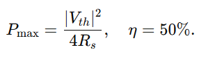
Conclusion (AC): Maximum power occurs when the load impedance equals the complex conjugate of the source impedance, ZL=Zs∗. Under this match,
Efficiency At Maximum Power Transfer
The efficiency of a circuit at maximum power transfer tells us how much of the total power generated by the source actually reaches the load.
Maximum Power Delivered to the Load:
For a DC circuit, the maximum power is delivered to the load when the load resistance RL equals the source resistance Rs:
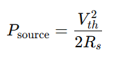
Total Power Supplied by the Source:
The total power supplied by the source under maximum power transfer is:
Calculating Maximum Efficiency
The efficiency is the ratio of power delivered to the load to the total power supplied by the source:
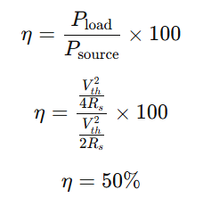
Interpretation:
- At maximum power transfer, the source delivers 50% of the generated power to the load.
- At other load conditions, the efficiency is lower, meaning less power is delivered to the load.
Practical Applications of Maximum Power Transfer Theorem
The theorem is applied in multiple areas, such as:
- Telecommunication: Antenna systems are designed for impedance matching to avoid signal loss.
- Audio Systems: Ensures speakers receive maximum power from amplifiers for clear and loud sound.
- Battery-Powered Devices: Determines optimal load resistance for maximum battery utilization.
- Electrical Engineering Labs: Used in experiments to verify the power transfer principle.
- Power Electronics: Optimizes the efficiency of inverters, rectifiers, and transformers.
Limitations of Maximum Power Transfer Theorem
- Efficiency Concern – The theorem states that maximum power is delivered to the load when the load resistance equals the source resistance. In this case, only 50% efficiency is achieved because half of the power is wasted in the source resistance.
- Not Suitable for Power Systems – In large power networks, applying this theorem is impractical since huge power losses would occur in transmission lines if source and load resistances were equal. In real systems, efficiency is prioritized over maximum power transfer.
- Applies to Linear, Bilateral Networks Only – The theorem is valid for linear and bilateral networks (with resistances, inductances, and capacitances). It does not apply directly to non-linear or unilateral elements such as diodes and transistors.
- Voltage Drop Issues – For practical circuits, designing with source and load resistances equal may cause excessive voltage drops across the source, making the output voltage too small for useful operation.
- Not Always Practical in AC Circuits – In AC networks, conjugate matching of load and source impedance is required, which is often complex and not feasible for high-power systems.
Important Notes About Maximum Power Transfer
- Efficiency is not maximum: Maximum power transfer does not mean maximum efficiency. Only 50% efficiency is achieved when load equals source resistance.
- Matching is key: Proper impedance or resistance matching is crucial in both AC and DC systems.
- Beyond theory: Practical designs sometimes prioritize efficiency or safety over maximum power transfer.
Summary
The Maximum Power Transfer Theorem is a fundamental concept in electronics that guides how to deliver the maximum power from a source to a load. By understanding the maximum power transfer formula, engineers can design circuits and devices for optimal performance.
Whether you are working with DC circuits, AC systems, or audio electronics, this theorem ensures efficient power usage, better performance, and reliable operation.
Related Articles: