Inrush current is the peak or maximum current that an electrical circuit draws when turned on. It can last for 3 to 10 cycles of the input waveform. The magnitude of the Inrush current is much higher than the steady-state current of the circuit, and this high current can damage the equipment. Devices with magnetic cores, such as transformers, motors, ballasts, etc., draw inrush current. Other names of inrush current are Inrush surge current and Switch-on surge current.
Inrush, Peak, and Steady State Current
The inrush current graph is shown below.
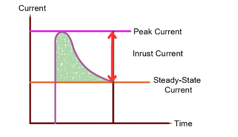
Peak Current: The maximum value of current drawn by the circuit during the positive or negative cycle of the waveform.
Steady-State Current: When the rate of change of current di/dt becomes constant, the circuit draws constant current. This state of the current is called steady state current.
Inrush Current: The duration of the inrush current is the time between peak and steady state.
Reasons for Inrush Current
The following factors contribute to the occurrence of inrush current:
- Magnetic Saturation: The transformers and motors have a magnetic core, and when voltage is applied, a rapid change in the magnetic flux occurs in the magnetic core, drawing a large inrush current.
- Residual Flux: When devices with magnetic cores are switched off, the flux in the core should return to zero. However, some flux is left, which is known as residual magnetism. This residual flux causes an inrush current when power is applied to energize the device.
- Charging Capacitors: The capacitors have almost zero impedance when power is applied to them. This creates a short circuit initially when the capacitor is powered up. Therefore, the capacitors draw a large inrush current of about 8 to 10 times the rated current.
Characteristics of Inrush Current
- Transient Nature: The duration of the signal is short, ranging from a few milliseconds to a few seconds, depending on device characteristics.
- It appears to last for a short span.
- It exceeds the circuit or device’s rated value. Inrush current can significantly exceed the steady-state current of a device.
- Nonlinear Behavior: During the inrush period, the relationship between voltage and current is often not linear. This nonlinear behavior creates harmonics in the system.
Examples of Electrical Loads that draw Inrush Current
- Incandescent Lamp
- Induction Motor Starting
- Transformer Charging
- SMPS-based power supplies
- LED Drivers
- Gas discharge Lamps
- Fluorescent lamps
Inrush Current in Transformer
Transformer inrush or surge current is the maximum instantaneous current that a transformer draws when there is no load or the secondary side is in an open circuit condition. The high current can damage the magnetic properties of the transformer’s core and cause the upstream breaker to trip. You may be curious to know how much inrush current the transformer draws. It may be 8 to 12 times the rated current or even more.
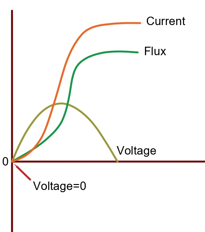
The magnitude of the inrush current depends on the point of the AC wave at which the transformer energizes. If the transformer turns on at the peak of the AC voltage in no-load condition, there will be no inrush current during start-up. This is because the magnetizing current lags the voltage by 90 degrees. However, if the transformer turns on when the AC voltage passes through zero, the inrush current’s value will be very high. This value can even exceed the saturation current, which is shown in the image below:
Inrush Current in Induction Motor
Like a transformer, an induction motor does not have a continuous magnetic path. The reluctance of the induction motor is high because of the air gap between the rotor and the stator. This high reluctance requires a high magnetizing current to produce the rotating magnetic field when starting. The diagram below illustrates the full voltage starting characteristics of the motor.
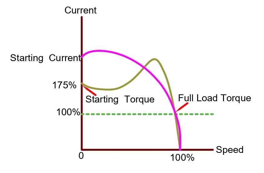
The diagram shows that both the starting current and starting torque are very high at the beginning, which can damage the motor’s electrical and mechanical systems. The high starting current can cause harm to the electrical system, while the initial high torque can affect the mechanical system. To avoid these issues, star delta starters, soft starters, and variable frequency drives are used to limit the current.
How to limit the Inrush Current?
It is essential to consider the inrush current in induction motors, transformers, and electronic circuits with inductors, capacitors, or cores. The inrush current is the highest peak current experienced in the system and can be twice or ten times the normal rated current. This sudden surge of current can damage the device. For instance, an inrush current can cause the transformer’s circuit breaker to trip every time it turns on. While adjusting the breaker tolerance may help, the components should be able to withstand the peak value during in-rush.
When designing an electronic circuit or PCB, it is crucial to consider the inrush current that specific components may be subjected to. While some components can withstand high levels of inrush current for short periods, others may become damaged or overheated. To avoid this, using an inrush current protection circuit in your design is recommended.
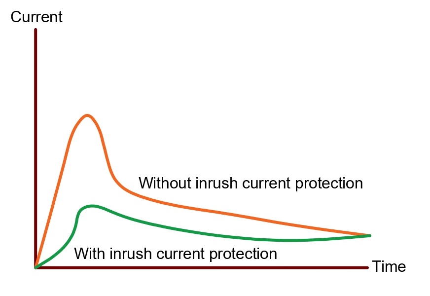
For protection against inrush current, you can use either an active or passive device. The choice of protection depends on the frequency of the inrush current, performance, cost, and reliability.
An NTC thermistor (Negative Temperature Coefficient) is a type of passive device that works like an electrical resistor. It has a high resistance at low temperatures and connects in series with the power supply input line. The NTC limits the inrush current when you turn on a device. As current flows, the thermistor’s temperature rises, which reduces its resistance. This allows a steady current to flow into the circuit. NTC thermistors are commonly used for current limiting due to their simple design and low cost. However, they may not be reliable in extreme weather conditions.
Active devices such as Soft Starters, voltage regulators, and DC/DC converters are sensitive components that switch high incoming current, making them expensive and bulky additions to a circuit or system.
How to measure Inrush Current?
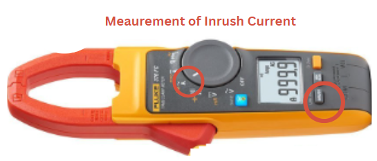
Several clamp meters (multimeters) are available that allow inrush current measurement. For instance, the Fluke 376 FC True-RMS Clamp meter can measure it. Sometimes, the inrush current might display a value that exceeds the circuit breaker’s rating, but the breaker does not trip. This happens because circuit breakers operate on an inverse time versus current curve. For instance, if you use a 100-amp circuit breaker, the current, which is more than 100 amps, should flow through the circuit breaker for a duration exceeding its rated time.

To measure the inrush current, follow the steps mentioned below:
- Before performing any tests, it is essential to ensure that the device to test is turned off.
- Rotate the dial until you reach the Hz-Ã symbol and set it accordingly.
- Insert the live wire into the clamp meter jaw or use a probe connected to it.
- Press the button for the inrush current on the clamp meter, as shown in the image above.
- Turn on the device being tested. The inrush current value will be displayed on the meter.
Conclusion
It is crucial to comprehend and handle inrush current to protect electrical components. Limiting the inrush current guarantees that the equipment operates correctly and prevents interruptions in power distribution systems. Techniques like soft starting, which involves gradually increasing the voltage supplied to the device, or using inrush current limiters can assist in reducing the impact of inrush current.