A clamp meter—also called a tong tester—is a widely used electrical testing tool that makes current measurement simple, quick, and safe. The clamp meter working principle is based on magnetic induction, which allows it to measure current without directly touching or disconnecting wires.
Unlike traditional meters that require breaking the circuit, a clamp meter measures current by detecting the magnetic field around a live conductor. This makes it an essential tool for electricians, technicians, and engineers who need to troubleshoot or test electrical systems safely.
What is a Clamp Meter?
Definition:
A clamp meter is a handheld device used to measure current flowing through a live conductor without using test leads. It works on the principle of detecting the magnetic field generated by the flowing current and then converting it into a readable value.
Because it does not require breaking the circuit, the clamp meter allows fast, convenient, and safe measurement of AC or DC current.
Why Clamp Meters are Popular
Safety
Traditional methods required cutting into wires or making direct contact with the circuit. A clamp meter eliminates this risk by simply clamping around the conductor.
Convenience
There’s no need to power down the system or disconnect wires. Measurements can be taken on live circuits, saving time during inspections or troubleshooting.
Key Specifications of a Clamp Meter
Specifications vary depending on the model and manufacturer, but here’s a general idea (using FLUKE as an example):
- AC Current Range: 40 A – 400 A (some models up to 1400 A)
- DC Current Range: 40 A – 400 A
- AC Voltage Range: Up to 600 V
- DC Voltage Range: Up to 600 V
- Resistance Range: 400 Ω – 40 kΩ
- Capacitance Range: 0 – 1000 µF
- Frequency Range: 5 Hz – 500 Hz
- Continuity: ≤ 30 Ω
- Temperature Measurement: -10°C to 400°C (for some models)
- True RMS: Available in advanced models for accurate readings
- Extra Features: Backlight, data hold, auto-range, and overload protection
Clamp Meter Working Principle
A clamp meter allows electricians and technicians to measure current without directly touching the conductor. It works by detecting the magnetic field created when electric current flows through a wire. This feature makes the clamp meter both safe and convenient for live-circuit measurements.
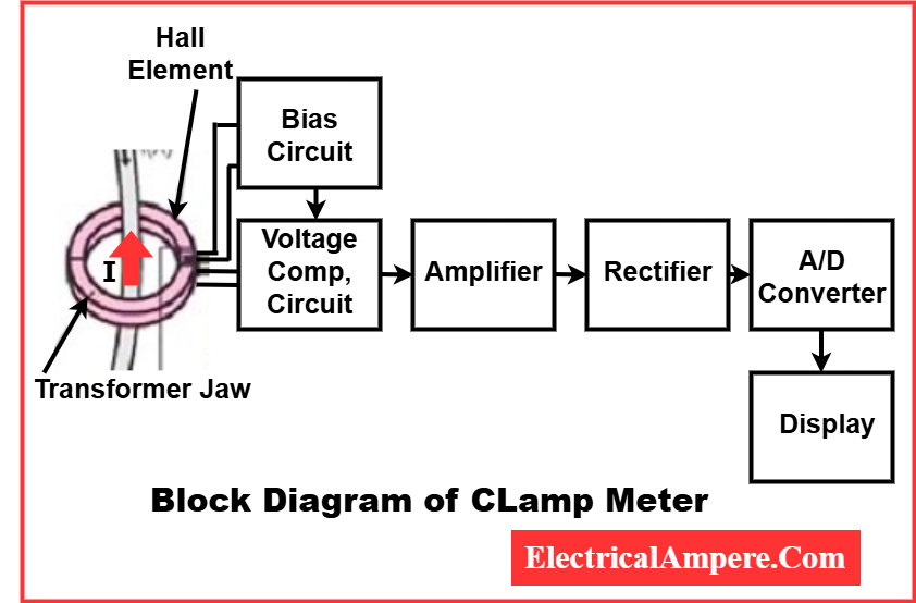
How AC Clamp Meters Work
AC clamp meters rely on a current transformer (CT) embedded in the jaws:
- Magnetic Field Creation:
When alternating current flows through a conductor, it generates a changing magnetic field around the wire. - Current Transformer in Jaws:
The meter’s jaws contain a ferromagnetic core with a secondary coil, forming a current transformer. - Electromagnetic Induction:
The changing magnetic field intersects the secondary coil, inducing a small AC current proportional to the wire’s current. - Voltage Conversion and Display:
This induced current is converted into a voltage, processed by the meter’s electronics, and displayed as the AC current value on the LCD.
How DC Clamp Meters Work
DC current is constant and does not produce a changing magnetic field, so Hall Effect sensors are used instead:
- Magnetic Field Detection:
The Hall Effect sensor directly senses the magnetic field generated by the DC current. - Voltage Generation:
The sensor produces a voltage proportional to the strength of the magnetic field. - Processing and Display:
This voltage is then processed by the meter circuitry to display the DC current on the screen.
Key Principles Behind Clamp Meters
- Magnetic Induction (AC): A varying magnetic field generates a current in a nearby coil.
- Ampere’s Right-Hand Rule: Magnetic field lines form concentric circles around a current-carrying conductor, with field strength proportional to current.
- Hall Effect (DC): A magnetic field applied to a semiconductor produces a voltage proportional to the field strength, enabling DC current measurement.
By combining these principles, clamp meters provide accurate, contactless current measurement for both AC and DC circuits, making them essential tools for industrial, commercial, and residential electrical work.
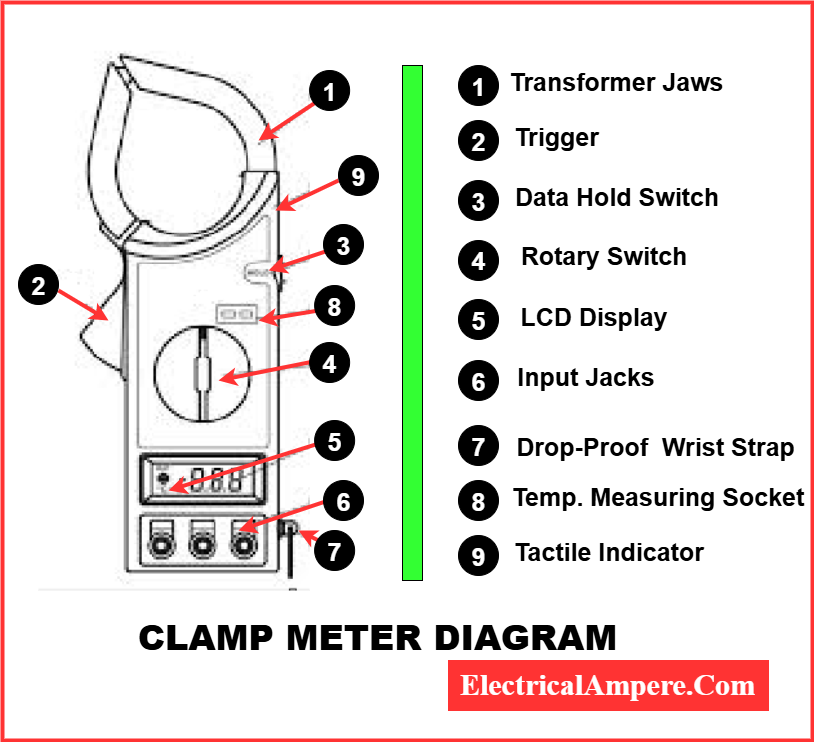
Construction of a Clamp Meter
A clamp meter is built from several essential components, each contributing to accurate and safe current measurement. The main parts include:
- Jaws / Transformer Clamps – Detect magnetic field around the conductor.
- Clamp Opening Trigger – Opens or closes the jaws.
- Power Switch – Turns the meter on or off.
- Backlight Button – Lights up the LCD for dark environments.
- Hold Button – Freezes the last reading for convenience.
- LCD Display – Shows measured values.
- Input Terminals – For additional voltage, resistance, and continuity tests.
- Rotary Switch – Selects the measurement mode (AC/DC, resistance, etc.).
The diagram below provides a visual representation of these components, helping you understand the structure and functionality of a clamp meter.
Types of Clamp Meters
Clamp meters are available in different types depending on measurement needs:
- AC Clamp Meter (Current Transformer Type): Measures only AC current.
- Hall Effect Clamp Meter: Measures both AC and DC current.
- Flexible Clamp Meter (Rogowski Coil): Used in tight spaces, measures AC current.
- DC Clamp Meter: Specially designed for DC current measurement using Hall Effect.
Precautions for Using a Clamp Meter
To ensure safe and accurate measurements, follow these precautions when using a clamp meter:
- Zero Adjustment:
Before starting any measurement, make sure the meter pointer is properly set to zero using the adjuster. - Select the Correct Range:
Always choose the appropriate measurement range on the meter. If uncertain, select a higher range to prevent damage—for example, set the voltage range to 750 V instead of a lower setting. - Current Measurement:
When measuring current, ensure the meter is connected correctly in series with the circuit. - Avoid Measuring Resistance on Live Circuits:
Never attempt to measure resistance if there is voltage present in the circuit, as this can damage the meter or cause inaccurate readings. - Safety First:
Keep your hands and fingers away from live conductors, especially while measuring high voltage, to avoid electric shock.
By following these precautions, you can ensure accurate readings and maintain personal safety while using the clamp meter.
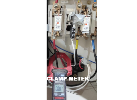
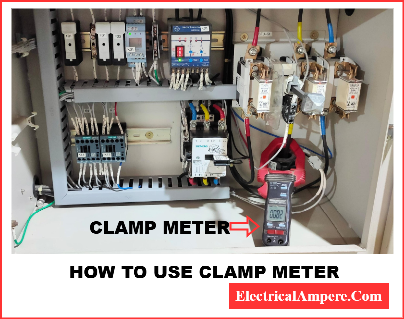
How to Use a Clamp Meter
Using a clamp meter is simple:
- Power on the meter and select the correct function.
- Open the clamp trigger and place the jaws around the conductor.
- Ensure proper spacing (about 2.5 cm) from other conductors to avoid interference.
- Read the measurement displayed on the LCD.
- Use the hold function if you need to record the value.
Applications of Clamp Meters
Clamp meters are used in almost every electrical field:
- Measuring high current safely (beyond 10 A, where multimeters struggle).
- Troubleshooting industrial control panels and HVAC systems.
- Inspecting commercial and residential wiring.
- Performing preventive maintenance in electrical installations.
- Training and assisting electricians with real-time current measurements.
Clamp Meter vs Multimeter
| Feature | Clamp Meter | Multimeter |
| Primary Use | Measures current | Measures voltage, resistance, and low current |
| Current Range | High current (up to 1400 A) | Limited (usually <10 A) |
| Safety | No need to break circuit | Requires contact with circuit |
| Accuracy | Lower than multimeter | Higher accuracy for small values |
| Best For | Industrial and field work | Electronic circuits and lab use |
Conclusion
The working principle of clamp meter makes it one of the safest tools for electrical testing. By relying on magnetic induction, a clamp meter enables quick and safe current measurement without cutting into wires or shutting down power.
While a multimeter is more accurate for low-current and electronic work, clamp meters are indispensable for measuring high current in live systems.
For professionals in industrial, commercial, or residential systems, a clamp meter is not just convenient—it’s a safety essential.
Understanding the clamp meter working principle helps electricians and engineers make the most of this versatile instrument.
Related Articles: