Understanding how magnetic fields interact inside a DC machine is crucial for optimizing performance and preventing losses. One such phenomenon is the armature reaction — a key concept that affects voltage, commutation, and machine efficiency. In this article, you’ll learn what armature reaction is, why it occurs, and how engineers overcome its effects in practical machines.
What is Armature Reaction?
Armature reaction refers to the effect of the magnetic field produced by the armature current on the main magnetic field of the DC machine. A DC machine has two magnetic fluxes: armature and main field. The effect of armature flux on the main field is called armature reaction.
To fully understand how armature reaction impacts the magnetic field, it’s important to first learn about MNA (Magnetic Neutral Axis) and GNA (Geometric Neutral Axis)—two reference axes crucial to flux alignment in DC machines.
MNA and GNA in DC Machine Explained
When the armature conductors cut the magnetic field lines, EMF is induced. However, there is a particular axis or plane where the armature conductors move parallel to the flux lines and do not cut them. This results in no EMF being generated in the conductors. This axis is called the Magnetic Neutral Axis (MNA). The brushes are always placed along the MNA because the reversal of current in the armature conductors occurs along this axis.
The Geometrical Neutral Axis, commonly abbreviated as GNA, can be defined as an axis that is positioned perpendicular to the stator field axis. In other words, this axis passes through the center of the stator cross-section.
Effect of Armature Reaction on MNA and GNA
The figure below clearly illustrates the impact of the armature reaction. When the field winding is energized, and no current flows through the armature conductors, the magnetic flux lines of the field poles are aligned symmetrically with the polar axis. The ‘Magnetic Neutral Axis’ (M.N.A.) is aligned with the ‘Geometric Neutral Axis’ (G.N.A.).

However, when current flows through the armature, the armature flux lines appear, and the field poles are de-energized. The image below displays the armature flux lines due to the armature current.
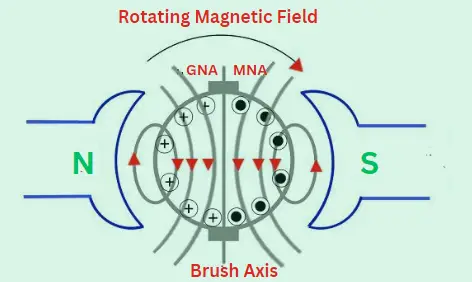
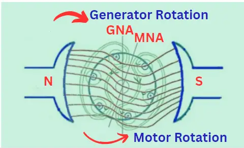
When a DC machine operates, the fluxes – one due to the armature conductors and the other due to the field winding – are present simultaneously. The armature flux overlaps with the main field flux, which causes a disturbance in the main field flux. This phenomenon is known as the armature reaction in DC machines, as shown in the image below.
Adverse Effects of Armature Reaction
- Armature reaction weakens the main flux, reducing the voltage generated in a DC generator and the torque in the DC motor.
- Armature reaction causes the main flux to distort, which results in a shift in the position of the M.N.A. (M.N.A. is perpendicular to the flux lines of the main field flux). To avoid sparking at the surface of brushes, it is necessary to place them on the M.N.A. Due to the armature reaction, it becomes difficult to determine the exact position of the MNA accurately.
For a loaded DC generator, the MNA will shift in the direction of rotation. Conversely, for a loaded DC motor, the MNA will shift in the opposite direction of rotation.
How to Reduce Armature Reaction in DC Machines
Compensating winding and interpoles are utilized in large DC machines to mitigate the harmful effects of armature reaction, and no special measures are taken for small machines with a capacity of up to a few kilowatts.
Compensating winding
It is known that the armature reaction occurs due to the presence of armature flux, which is produced by the current flowing through armature conductors. To nullify the armature field, a compensating winding can be placed near the armature winding and carry the same current but in the opposite direction. This winding is located on the pole faces and connected in series with the armature winding to carry the current in the opposite direction.
Interpoles
Interpoles are small auxiliary poles that are placed between the main field poles. The winding on the interpoles is connected in series with the armature. Each interpole is wound so that its magnetic polarity is the same as that of the main pole ahead of it. The purpose of the interpoles is to nullify the quadrature axis armature flux.
Conclusion
Armature reaction in DC machines plays a critical role in determining the performance and efficiency of both generators and motors. It arises due to the interaction between the armature flux and the main field flux, leading to distortion and weakening of the magnetic field. This effect causes a shift in the Magnetic Neutral Axis (MNA), potentially resulting in sparking and operational instability if not addressed.
Frequently Asked Questions (FAQs)
Armature reaction in a DC machine refers to the impact of the magnetic field produced by the armature current on the main magnetic field. This interaction distorts and weakens the main field, leading to reduced efficiency and performance.
The armature reaction in a DC generator distorts the main flux, weakens the generated voltage, and causes the magnetic neutral axis (MNA) to shift. This can lead to poor commutation and sparking at the brushes.
MNA stands for Magnetic Neutral Axis, the axis where no EMF is induced in the armature conductors. GNA stands for Geometrical Neutral Axis, the axis perpendicular to the main field axis. Under ideal conditions, MNA and GNA coincide, but due to distortion of main magnetic field, MNA shifts from GNA.
Use compensating windings and interpoles in large machines. They counteract the armature flux and restore field symmetry.
Interpoles cancel the effect of interaction between armature and field flux in the commutation zone, preventing sparking and improving brush performance.
Related Article:
- DC Generator: Types, Parts, Working Principle, Applications, Diagrams
- DC Machine: Definition, Basic structure, Construction & Equivalent circuit
- DC Generator Equations and Formulas
- Rotating Electrical Machines: Types, Examples,
- Electric Machines: Definition, Types, Working, Formulas, Examples
- Synchronous Machine