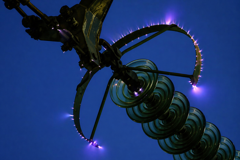
The corona discharge effect is a critical phenomenon in high-voltage engineering, particularly in power transmission and distribution systems. It occurs when the electric field intensity around a conductor exceeds the dielectric strength of the surrounding air, leading to a partial discharge. This results in a faint violet glow, audible hissing, and significant energy loss.
What is the Corona Effect?
The Corona Effect is a localized electrical discharge that occurs when the air surrounding a high-voltage conductor becomes ionized. While we often treat air as a perfect insulator, it naturally contains “seed” electrons and ions created by cosmic radiation and radioactivity.
When a high-potential electric field is established between conductors, these ambient free electrons are subjected to intense electrostatic force, causing them to accelerate. As these high-velocity electrons collide with neutral air molecules, they dislodge additional electrons in a cumulative chain reaction known as an Electron Avalanche.
This ionization process begins the moment the potential gradient reaches the Critical Disruptive Voltage (Vd). Under Standard Temperature and Pressure (STP), the dielectric strength of air is approximately 30 kV/cm. At this specific threshold, the air loses its insulating properties and transforms into a conducting medium, allowing electrical energy to “leak” into the atmosphere.
Indicators of Corona Discharge
Once the air is overstressed, the discharge manifests through several distinct physical markers:
- Visual signals: A faint violet or bluish glow around the conductor.
- Acoustic signals: A characteristic hissing or “cracking” sound.
- Chemical signals: The production of Ozone (O3), identifiable by its pungent smell.
Impact on High-Voltage Power Transmission
In modern power grids, electricity is transmitted over long distances using Extra High Voltage (EHV) to minimize current-related losses. However, as voltage levels increase, the risk of corona discharge becomes a primary concern for power engineers.
Corona discharge represents a significant non-ohmic energy loss, dissipating real power in the form of heat, light, and sound. Beyond reducing system efficiency, the chemical by-products (Ozone and Nitrous oxides) are highly corrosive. Over time, this can lead to the degradation of conductors and insulator hardware, making the management of the corona threshold a critical factor in grid reliability and long-term asset integrity.
Critical Conditions for Corona Discharge
For the corona effect to manifest in a power system, two fundamental physical conditions must be met. These factors dictate whether the surrounding air will maintain its insulation or succumb to dielectric breakdown.
1. High Potential Difference
An alternating electrical potential difference must be applied across the transmission line. At low voltages, the electric field is insufficient to disturb the molecular structure of the air. However, as the potential increases, the air is subjected to intense dielectric stress.
2. Conductor Spacing vs. Diameter Ratio
The distance between conductors must be significantly larger than the conductor’s diameter. If the spacing is too small, a full spark-over or power arc will occur before the corona can stabilize. Proper spacing allows for the localized ionization characteristic of the corona discharge effect.
The Threshold: Critical Disruptive Voltage (Vd)
The transition from an insulating state to a conducting state is not gradual; it occurs at a specific mathematical threshold known as the Critical Disruptive Voltage (Vd).
- The 30 kV Benchmark: Under standard atmospheric conditions, when the potential difference exceeds approximately 30 kV/cm (peak), the field strength becomes high enough to ionize the air molecules.
- Ionization Phase: Once Vd is surpassed, the air surrounding the conductor becomes conductive. This localized breakdown results in a continuous flow of ions, manifesting as the “corona.”
The Impact of Increasing Voltage
If the line voltage continues to rise beyond the critical disruptive threshold, the intensity of the glow and noise increases. This is a direct indicator of escalating corona power loss. In high-voltage engineering, managing these levels is vital to prevent system inefficiency and the accelerated degradation of transmission hardware.
Primary Factors Influencing Corona Loss
While line voltage is the fundamental trigger for electrical corona, the severity of the discharge is dictated by the interaction between the conductor’s physical properties and its environment.
1. Atmospheric Conditions and Air Density
The breakdown strength of air is not constant; it is directly proportional to the air density.
- Air Density Factor (δ) : In high-altitude regions or during high-temperature periods, the air becomes “thinner,” reducing its dielectric strength and lowering the Critical Disruptive Voltage.
- Weather Extremes: During stormy, foggy, or rainy conditions, the concentration of free ions in the atmosphere increases. Moisture and wind accelerate the ionization process, making corona discharge significantly more aggressive than on clear, fair-weather days.
2. Conductor Physical Characteristics
The geometry and surface quality of the cable are vital in determining the onset of the corona discharge effect.
- Diameter Relationship: Corona intensity is inversely proportional to the conductor diameter. Increasing the size of the conductor lowers the electric field gradient at its surface, which is why larger or bundled conductors are preferred for EHV lines.
- Surface Integrity: Roughness, mechanical scratches, or accumulated dirt act as points of high curvature. These irregularities concentrate the electric field, triggering localized “plumes” of discharge even at voltages below the theoretical breakdown limit.
3. Conductor Spacing and Dielectric Stress
The distance between conductors (D) must be carefully balanced against their radius (r).
- Spacing Threshold: For corona to exist, the spacing must be large enough to prevent a direct phase-to-phase arc.
- Gradient Reduction: As the spacing between lines increases, the electrostatic stress on the air molecules decreases. If the gap is sufficiently wide, the potential gradient may never reach the 30 kV/cm required for ionization, effectively eliminating corona in that segment of the line.
Impact of Corona Discharge on Power Systems
The corona discharge effect is more than just a visual phenomenon; it has measurable consequences on the efficiency, hardware longevity, and surrounding environment of a power network.
The dissipation of energy into the atmosphere through ionized air creates several operational challenges for high-voltage networks.
1. Significant Power Loss
The most direct impact is the dissipation of real power. Energy that should reach the consumer is instead wasted as heat, light, and sound. In Extra High Voltage (EHV) systems, the magnitude of this loss is mathematically defined by Peek’s Formula:
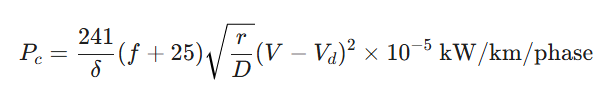
Where:
- Pc: Corona power loss in kW/km/phase.
- f: Supply frequency in Hz.
- δ: Air density correction factor.
- V: Operating voltage (RMS) in kV.
- Vd: Critical disruptive voltage (RMS) in kV.
- r: Radius of the conductor.
- D: Spacing between conductors.
This energy drain becomes a noticeable percentage of total line losses, particularly during foul weather when the air density factor (δ) fluctuates. Since the loss is proportional to the square of the difference between the operating voltage and the critical disruptive voltage (V – Vd)2, even a small increase in voltage beyond the threshold can lead to a massive spike in power waste.
2. Acoustic Noise and Mechanical Vibration
The ionization of air molecules creates a continuous “hissing” or “frying” sound. At very high voltages, the movement of ions can even induce mechanical vibrations in the conductors, which may lead to hardware fatigue over time.
3. Radio and Communication Interference
Corona discharge produces high-frequency electromagnetic waves. These pulses create “noise” that interferes with nearby radio, television, and communication signals. This is a critical design factor when routing transmission lines near residential or industrial communication hubs.
4. Ozone Formation and Chemical Corrosion
The electrical breakdown of air molecules (O2) leads to the liberation of Ozone (O3). In the presence of moisture, these gases can form corrosive nitric acid. This chemical reaction attacks the metal of the conductors and degrades the polymer or porcelain materials of insulators.
5. Transient Voltage Mitigation
While generally avoided, the corona effect offers one distinct advantage in power system protection. Corona acts as a natural “safety valve” during sudden voltage surges caused by lightning strikes or switching operations.
Because the corona loss increases exponentially with voltage, the discharge dissipates the energy of the high-voltage transient into the atmosphere. This reduces the “steepness” of the surge front, protecting downstream equipment from insulation failure.
Strategies to Reduce Corona Discharge
Because the corona discharge effect results in non-recoverable power loss and hardware degradation, high-voltage power networks must be designed to keep the potential gradient below the ionization threshold.
Engineers utilize the following proven strategies to control and minimize corona in transmission line:
1. Increasing Conductor Diameter
The electric field intensity at the surface of a conductor is inversely proportional to its radius. By increasing the conductor size, the voltage gradient is spread over a larger surface area. This reduces the dielectric stress on the surrounding air, thereby increasing the voltage level at which corona begins.
2. Implementing Bundled Conductors
In Extra High Voltage (EHV) and Ultra High Voltage (UHV) lines, simply increasing a single conductor’s size is often impractical due to weight and cost. Instead, bundled conductors (two or more sub-conductors per phase) are used.
- The Benefit: Bundling increases the Geometric Mean Radius (GMR) of the phase. This effectively “tricks” the electric field into behaving as if it were a much larger single conductor, significantly lowering the corona onset risk.
3. Optimizing Phase Spacing
Increasing the distance between the phase conductors reduces the electrostatic flux density between them. While larger spacing decreases the corona effect, it must be balanced against the increased cost of taller and wider transmission towers.
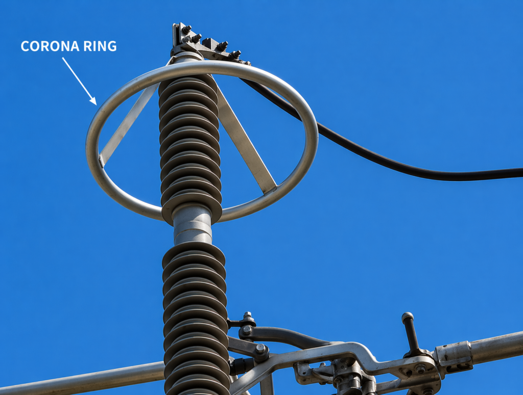
4. Utilization of Corona Rings
Electric fields naturally concentrate at “sharp” points, such as bolts, terminals, and insulator suspension hardware. Corona rings are circular metallic loops installed at these high-stress points.
- How they work: The ring is electrically connected to the high-voltage conductor and “rounds out” sharp edges. By creating a smooth, large-radius surface, the ring redistributes the electric charge over a wider area, preventing the localized ionization that leads to discharge.
5. Surface Maintenance and Cleaning
Since surface irregularities (nicks, scratches, or dirt) act as discharge points, maintaining “smooth” conductors is essential. In industrial or coastal areas, regular cleaning to remove salt deposits and pollutants helps maintain the conductor’s surface irregularity factor (m0), keeping the disruptive voltage high.
The Relationship Between Corona Discharge and Current
While voltage is the primary driver for the onset of the corona discharge effect, the behavior of current within the system provides a deeper look into the energy losses and electromagnetic impacts of this phenomenon.
The Role of Current in Ionization
In a high-voltage environment, the electrostatic field is the catalyst for ionization. However, once the Critical Disruptive Voltage is surpassed, a non-sinusoidal “corona current” begins to flow.
- Ion Flow: The current in a corona discharge consists of the movement of ions and electrons from the high-voltage conductor into the surrounding air.
- Harmonic Distortion: This current is characterized by high-frequency pulses. These pulses are a primary cause of Radio Interference (RI) and can introduce unwanted harmonics into the power system.
Current and Corona Power Losses
The interaction between system current and discharge intensity is a major factor in transmission efficiency.
- Energy Dissipation: As the intensity of the discharge increases, a larger portion of the line current is diverted into the atmosphere. This energy is lost as light (violet glow), acoustic energy (hissing), and thermal energy.
- Peek’s Formula Influence: Engineering calculations show that corona power loss increases as the system voltage moves further above the critical threshold. While line current (load current) does not directly “cause” corona, the thermal state of the conductor and the resulting ion density can influence the severity of the loss.
Current Management Strategies for Mitigation
Effectively managing corona effect electrical behavior requires a combination of design and operational maintenance:
- Harmonic Filtering: Installing specialized circuit components to mitigate the high-frequency interference caused by corona current, protecting sensitive nearby communication equipment.
- Thermal Monitoring: Maintaining the integrity of the transmission line helps prevent “hot spots.” Since temperature affects air density, managing the thermal load on the conductor helps stabilize the Air Density Factor (δ), which in turn keeps the corona onset voltage predictable.
- Load Balancing: Ensuring that the current is distributed evenly across bundled conductors to minimize localized points of high dielectric stress.
Direct Current (DC) Corona Discharge
While most transmission lines operate on Alternating Current (AC), Direct Current (DC) corona discharge is a critical factor in the design of modern HVDC systems. Unlike its AC counterpart, where the polarity cycles 50 or 60 times per second, DC corona maintains a constant polarity, leading to unique physical characteristics and ion behavior.
Fundamentals of DC Corona Discharge
DC corona occurs when a constant high-voltage potential is applied to an electrode system in an air-filled environment. This experimental phenomenon typically involves an active electrode (a sharp conductor where the field is concentrated) and a passive electrode (a flat or grounded surface).
Because the electric field does not cycle, a steady “space charge” of ions builds up around the conductor. The nature of the resulting discharge is heavily dependent on whether the DC voltage polarity is positive or negative.
Differences Between Positive and Negative Corona Discharge
The polarity of the DC voltage radically changes the visual and electrical signature of the corona discharge effect.
1. Positive Corona Discharge (Anode Corona)
When the conductor is at a positive potential, electrons are stripped from the surrounding air and accelerated toward the conductor.
- Visual Appearance: It manifests as a smooth, uniform, and faint bluish glow that consistently covers the surface of the active electrode.
- Characteristics: Positive corona is generally quieter but is a significant source of ozone (O3) production.
2. Negative Corona Discharge (Cathode Corona)
When the conductor is at a negative potential, electrons are ejected away from the conductor into the air.
- Visual Appearance: Unlike the smooth glow of the positive corona, negative corona results in a brighter, filamentary glow. These are often seen as concentrated “tufts” or “beads” of light at points of highest electric field strength.
- Characteristics: It is typically more aggressive, causing higher levels of Radio Interference (RI) and acoustic noise compared to positive DC corona.
Comparison of DC Corona Polarities
| Feature | Positive DC Corona | Negative DC Corona |
| Visual Appearance | Uniform, smooth bluish glow | Bright, filamentary “tufts” or beads |
| Noise Level | Relatively quiet / steady hiss | Higher acoustic noise / aggressive cracking |
| Interference | Low Radio Interference (RI) | High Radio Interference (RI) |
| Ozone (O3) Output | Higher production rates | Lower production rates |
DC Corona Discharge Characteristics
The behavior of corona in DC systems is defined by its specific current-voltage relationship and the “ion wind” it creates.
- Onset Voltage: This is the minimum voltage required to initiate the discharge. For DC systems, the onset voltage is highly sensitive to the shape and size of the electrodes, the gap distance, and atmospheric properties like pressure and humidity.
- Corona Current Rise: Once the applied voltage surpasses the onset threshold, the corona current begins to rise. In DC, this current-voltage curve is more stable than in AC, making it easier to monitor for insulation health.
- Unipolar Ion Flow: In DC systems, ions of the same polarity as the conductor are repelled and travel across the entire gap to the opposite electrode. This creates a constant “ion wind” that must be accounted for in the environmental impact assessments of HVDC transmission lines.
Conclusion
The corona discharge effect is a critical consideration in high-voltage engineering. A clear understanding of corona effect in electrical systems, especially corona effect transmission lines, helps engineers design efficient and reliable power networks. By controlling corona effect high voltage conditions, it is possible to reduce energy losses and enhance the performance of modern power systems.
Read Next: