Discover how a booster transformer helps regulate voltage in power and railway systems. Learn its working, advantages, and why booster transformers are essential for voltage stability and stray current control.
What is a Booster Transformer?
A booster transformer is a specialized type of transformer primarily used at the end of a power distribution line to increase or adjust the voltage to a required level. It plays a crucial role in regulating the voltage on a feeder that is located far from the main substation or main transformer. This makes booster transformers especially valuable in long-distance power transmission systems.
Working Principle of Booster Transformer
In a typical setup, the secondary winding of the booster transformer is connected in series with the power line, while its primary winding is energized from the secondary of a regulating transformer. The regulating transformer controls how much voltage is injected into the line.
The booster transformer diagram is shown in the image below.
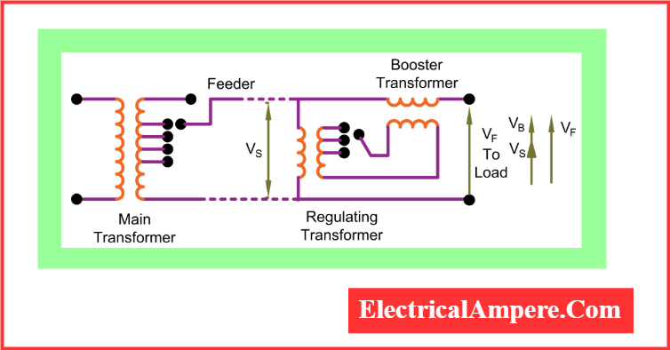
The regulating transformer’s output is arranged so that the voltage injected by the booster transformer (VB) is in phase with the main supply voltage (VS). By adjusting the taps on the regulating transformer, the voltage VB can be varied, effectively regulating the feeder voltage (VF).
This setup ensures that voltage stability is maintained along the feeder, especially in systems where voltage drops can occur due to long distances or heavy loads.
Example:
Suppose the voltage at the starting point of a feeder is 33 kV, but due to line drop, the voltage at a location 50 km away has fallen to 31.8 kV. In this case, the booster transformer will inject a secondary voltage of 1.2 kV in phase with the supply. As a result, the voltage at the end of the line becomes:
31.8 kV + 1.2 kV = 33 kV,
restoring the voltage to the desired level.
Methods of Connecting Booster Transformers
In electric traction systems, booster transformers are employed to reduce interference with nearby communication lines caused by stray return currents. These transformers can be connected using two primary methods:
- Rail-Connected Booster Transformer
- Booster Transformer with Return Feeder
1) Rail-Connected Booster Transformer
In a rail-connected booster transformer system, the primary winding of the booster transformer is connected in series with the overhead contact wire, while the secondary winding is connected in series with the railway tracks (rails). The schematic representation of this setup is shown in Figure 1.
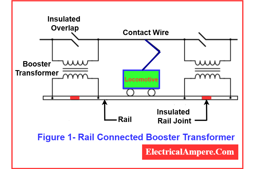
In this configuration, the current flowing through the contact wire also flows through the primary winding, inducing a voltage in the secondary winding. This induced voltage drives the return current to flow exclusively through the rails, effectively minimizing the stray current leakage into the earth and thus reducing electromagnetic interference with nearby communication lines.
Disadvantages of Rail-Connected Booster Transformer System:
- Insulated Rail Joints: The rail joints near the location of the transformer must be insulated. However, if insulation punctures occur, the rail joint may short-circuit the secondary winding, rendering the booster transformer ineffective.
- Increased Voltage Hazards: There can be an increase in potential difference between rails or between the rails and the ground. This poses safety risks for humans and animals in proximity.
This method is effective for reducing communication line interference but comes with operational challenges, especially related to insulation and safety.
2) Booster Transformer Using Return Feeder
The connection diagram of a booster transformer with a return feeder is shown in Figure-2.
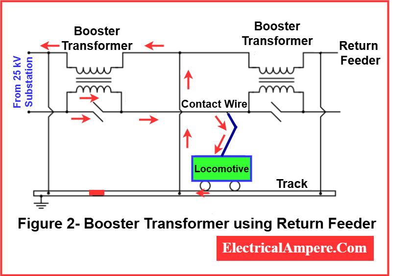
In this arrangement, the railway track is not utilized as the return path to the substation. Instead, a dedicated return feeder is provided alongside the contact wire, and all return current flows through this return feeder. This approach is significantly more effective than the rail-connected booster transformer setup and is therefore widely used in modern electric traction systems.
The booster transformer used in this configuration has a unity turn ratio (1:1). Its primary winding is connected in series with the contact wire, while the secondary winding is connected in series with the return feeder. The return feeder is linked to the rails at the midpoints between two booster transformers to ensure balanced current flow.
As the traction current passes through the contact wire and primary winding of the transformer, an equal amount of voltage is induced in the secondary winding. This induced voltage forces the return current to flow strictly through the return feeder, thereby eliminating earth leakage and reducing interference with nearby communication lines.
Disadvantages of Return Feeder Booster Transformer System:
- It is inserted in series with the traction circuit, which increases the overall impedance of the system.
- This increased impedance can lead to poor voltage regulation at the locomotive end.
- To mitigate this issue, feeding posts must be positioned closer together, or a series capacitor of appropriate rating may be used to improve voltage regulation.
Despite this limitation, the booster transformer with return feeder method remains the preferred choice in electric traction systems, particularly for long-distance and high-speed railway networks.
Precautions in Connecting Booster Transformer
When integrating a booster transformer into a traction circuit, the following safety and operational precautions must be observed to ensure reliable performance and to prevent damage under fault conditions:
- Withstand High Mechanical Stress
The transformer must be designed to endure severe mechanical stresses caused by fault currents, which can reach thousands of amperes during short-circuit conditions. - Proper Insulation Levels
- The primary winding insulation should be rated for 25 kV, as it deals with the high voltage from the contact wire.
- The secondary winding insulation should be rated for 3 kV, since it can experience high induced voltage under fault or unbalanced conditions.
- Strategic Placement
The transformer should not be installed near signal systems or areas where trains frequently stop. This prevents electromagnetic interference with signaling equipment and ensures passenger safety.
Taking these precautions ensures the booster transformer operates safely and effectively in electric traction systems, while minimizing risks of insulation failure, system malfunction, and signal interference.
Key Advantages
One major advantage of this configuration is that the regulating transformer and associated equipment work independently of the main transformer. This means that even if the regulating transformer fails, the main transformer remains in service, ensuring continuity in power supply.
Additionally, the regulating transformer is designed with a much smaller capacity compared to the main transformer, making the system more economical.
Application in Railway Systems
In railway electrification, booster transformers are used as traction transformers to reduce the flow of stray currents. These voltage booster transformers help prevent stray currents from interfering with communication systems and protect the sensitive electronic equipment on passing trains. This makes them an essential component in maintaining the integrity and safety of modern electrified railway networks.
Read Next: