Explore what phase angle is, how to measure it using various methods, and the key formulas involved. Learn about phase angle in electrical circuits with clear examples.
Before understanding the phase angle, let us first learn what phase is and how it plays a role in AC signals.
What is Phase?
In electrical engineering, phase refers to the position of a point in time on a waveform cycle. It describes the fraction of the wave cycle that has elapsed relative to the origin. When comparing two waveforms of the same frequency, the difference in their phases is referred to as the phase difference.
Phase Angle
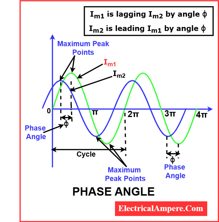
Phase angle is the angular displacement between two sinusoidal waveforms of the same frequency. It is typically the angle by which one waveform leads or lags another.
Definition:
The phase angle is the angular measure, in degrees or radians, between two waveforms of the same frequency.
It is a complex quantity. A periodic waveform can be represented as:

Where:
- Ais the magnitude
- θ is the phase angle
The phase angle θ is measured in degrees or radians.
Symbol:
The symbol of phase angle is generally denoted by φ (phi) or θ (theta).
Phase Angle in Electrical Circuits
In alternating current (AC) circuits, the voltage and current waveforms may not reach their peak values at the same time due to the presence of reactive components. This time shift is represented by the phase angle in electrical circuits.
- In a purely resistive circuit, voltage and current are in phase (phase angle = 0°).
- In an inductive circuit, current lags voltage (positive phase angle).
- In a capacitive circuit, current leads voltage (negative phase angle).
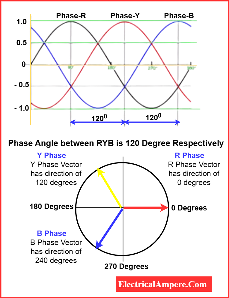
3-Phase Angle in Power Systems
In a 3-phase electrical system, three sinusoidal voltages or currents are separated by 120 electrical degrees. The 3-phase angle between them ensures balanced power delivery and is fundamental in high-power applications.
Phase Angle Formula
Two commonly used formulas for phase angle are:
1. Based on Impedance:
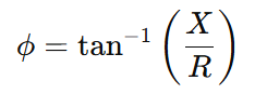
If the reactance and resistance are known, the following formula can be used to determine the phase angle
Where:
- ϕ= phase angle
- X= reactance (inductive or capacitive)
- R = resistance
If the impedance and resistance are known, the following formula can be used to determine the phase angle.
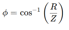
Where:
- ϕ = phase angle (in degrees or radians)
- R = resistance (in ohms)
- Z= impedance (in ohms)
2. Based on Power Factor:
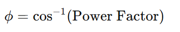
These formulas are used for determining the phase relationship between voltage and current.
Phase Angle Examples
Example 1:
In an R-L circuit, if current lags voltage by 45°, the phase angle is +45°.
Example 2:
In a resistive circuit, where voltage and current are in phase, the phase angle is 0°.
How to Determine Phase Angle
Phase angle can be measured using:
- Time-domain measurement:
- Impedance values: Apply the tangent-based formula.
- Power factor: Use inverse cosine.
- Phasor diagram: Measure the angle between vectors.
1. Phase Angle from Time Difference:
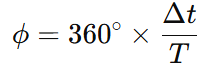
Where:
- Δt = time delay between voltage and current waveform peaks
- T= time period of one complete waveform
This method is suitable for time-based waveform analysis using oscilloscopes.
Example:
Two signals of frequency 50 Hz have a time difference (Δt) of 2 milliseconds (0.002 s).
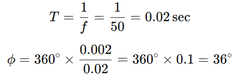
There is a 36° phase difference between the two signals.
2. Using Impedance Values
In an AC circuit, especially one that includes resistance (R) and reactance (X), the phase angle ϕ can be calculated using the tangent-based formula:
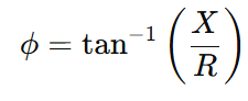
Where:
- ϕ= phase angle (in degrees or radians)
- X= reactance (inductive or capacitive)
- R= resistance
Example:
An R-L circuit has:
- Resistance, R=10 Ω
- Inductive reactance, XL=10 Ω
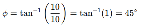
The current lags the voltage by 45° in this circuit.
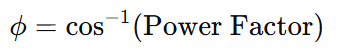
3. Using Power Factor
The power factor (pf) of an AC circuit is the cosine of the phase angle:
Example:
If the power factor of a circuit is 0.8 lagging:
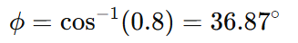
The current lags the voltage by 36.87°.
4. Using a Phasor Diagram
A phasor diagram represents AC quantities as rotating vectors. The angle between the voltage and current phasors directly shows the phase angle.
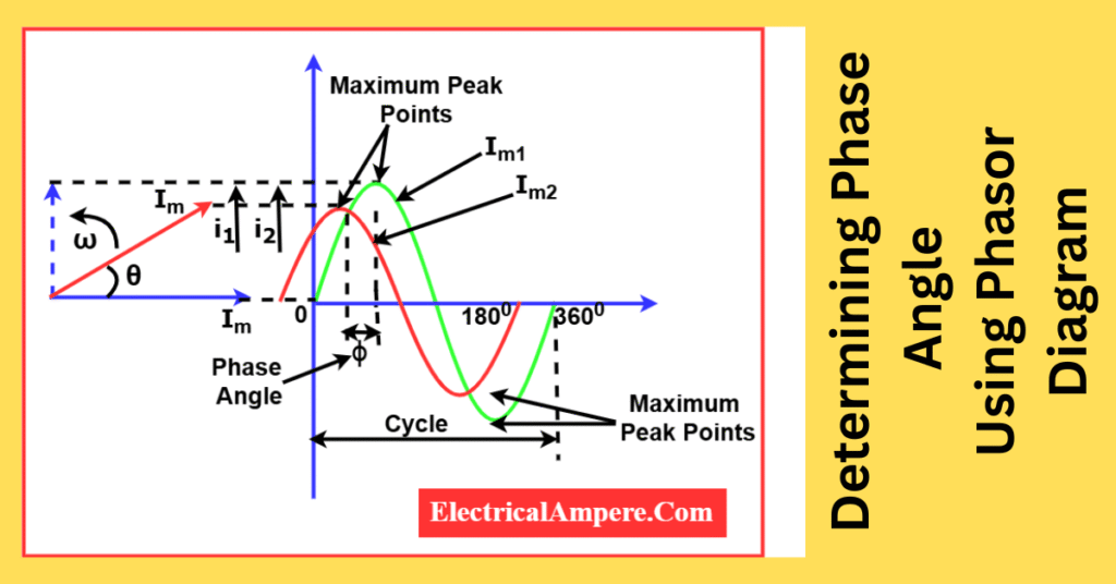
Example:
In a circuit with a sinusoidal voltage and lagging current, if a phasor diagram shows a 60° angle between them, then:
Current lags voltage by 60°.
Summary Table- Methods of Phase Angle Measurement
| Method | Formula |
|---|---|
| Impedance | ϕ=tan−1(X/R) |
| Power Factor | ϕ=cos−1(pf) |
| Phasor Diagram | Measured directly |
| Time-Domain | ϕ=360∘×(Δt/T) |
Conclusion
Phase angle is a critical parameter in the analysis of AC circuits. It affects power calculations, system stability, and circuit design. Understanding its definition, formulas, and methods of determination is essential for accurate electrical analysis.
Frequently Asked Questions (FAQs)
Q1. What is a phase angle?
A phase angle is the angular shift between two sinusoidal waveforms. It shows how much one wave leads or lags behind the other over time.
Q2. How do you represent a periodic waveform?
A periodic wave is written as:
A∠θA
Where:
- A is the amplitude or magnitude
- θ is the phase angle
Q3. Is the phase angle a complex value?
Yes. In phasor analysis, the phase angle is a part of a complex number that represents both magnitude and phase shift.
Q4. What units are used to measure phase angle?
Phase angle is measured in degrees (°) or radians (rad).
Q5. How many degrees are there in one full cycle of a waveform?
One complete cycle on a Cartesian graph spans 360 degrees of phase angle.
Read Next: