Maintaining a constant voltage at different levels in a power system is crucial. Several techniques are available for voltage control at different levels. An Automatic Voltage Regulator (AVR) regulates the field current and maintains the constant output voltage of the generator.
Generators in a power station experience fluctuations in their terminal voltage due to changes in the supplied load or other factors. Every generator has an automatic voltage regulator (AVR) to counteract this. Various types of AVR are available, with earlier models being electromechanical systems, while modern versions use solid-state devices such as thyristors.
Working Principle Of An Automatic Voltage Regulator
An Automatic Voltage Regulator functions on the principle of the feedback control system. It works by measuring the output voltage of a generator using a Potential Transformer. This output voltage is then rectified, filtered, and compared to a set reference voltage using a comparator. The difference between the generator’s output voltage and the reference voltage is the error voltage. This error voltage is amplified and used to control the generator’s excitation.
An automatic voltage regulator (AVR) uses excitation control to keep the generator’s output voltage constant by varying the alternator’s field current—the generator terminal voltage changes when the field current changes the field flux.
The generator’s output voltage is directly related to the excitation current. If you control the excitation system with an Automatic Voltage Regulator (AVR) to increase the excitation current, the magnetic flux will also increase, leading to a higher output voltage.
When the excitation current decreases, the magnetic flux decreases, resulting in a lower output voltage. This relationship enables accurate regulation of the alternator’s output voltage, a crucial factor in sustaining a stable and controlled voltage supply in power generation and distribution systems. The Automatic Voltage Regulator(AVR) block diagram is shown in the image below.
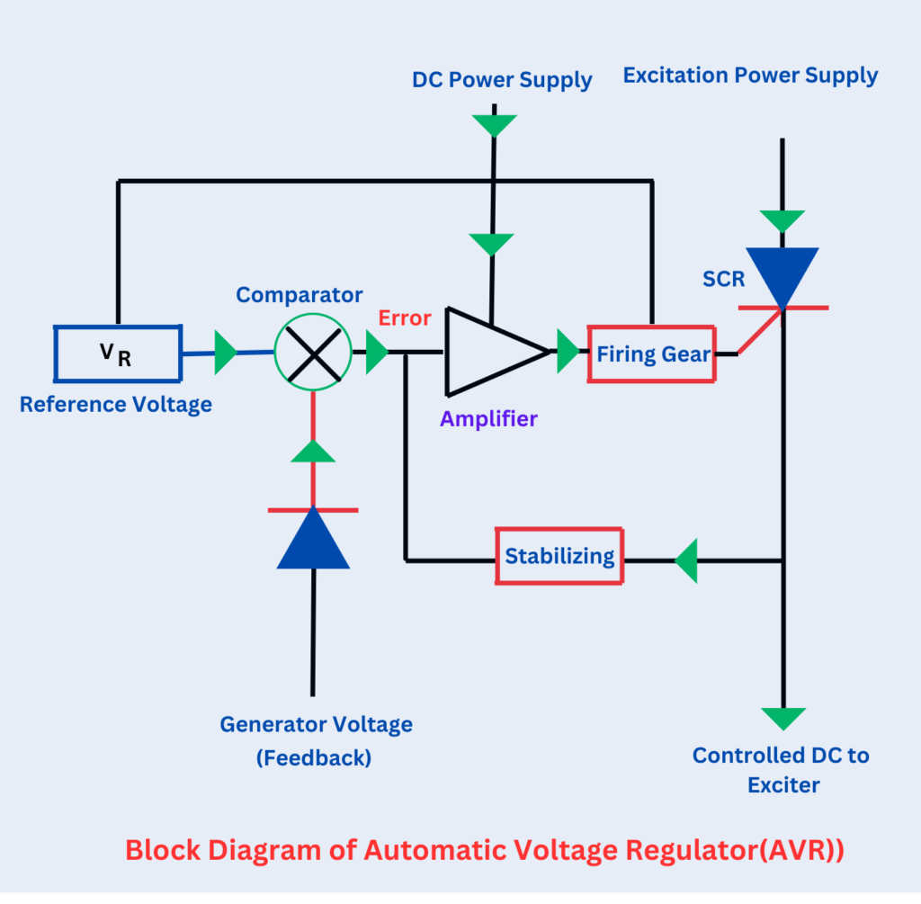
Voltage Sensing: The Automatic Voltage Regulator (AVR) consistently monitors the generator’s terminal voltage. This monitoring is usually carried out using a potential transformer (PT) or a voltage transformer (VT) to step down the generator’s voltage to a manageable level for the AVR to process.
Comparison and Error Detection: The AVR compares the sensed voltage to a reference voltage or setpoint. This reference voltage is the set point of the generator’s desired output voltage that the generator should maintain. Any variation from this setpoint voltage is considered an error.
Error Amplification: An error amplifier amplifies the signal to regulate the generator’s excitation system.
Excitation System Control: The excitation system is a critical component that provides the necessary field current to the generator’s rotor windings. This field current determines the strength of the magnetic field and, hence, the generator’s output voltage. The Automatic Voltage Regulator (AVR) adjusts the excitation system by increasing or decreasing the field current based on the error signal received to ensure that the output voltage is maintained at the desired level.
Adjustment of Field Current: When the Automatic Voltage Regulator (AVR) senses that the voltage is lower than the desired voltage, it increases the field current to strengthen the magnetic field, which increases the generator’s terminal voltage. On the other hand, if the sensed voltage is higher than the setpoint voltage, the AVR decreases the field current, which weakens the magnetic field and lowers the generator’s voltage.
Feedback Loop: The AVR continuously monitors and adjusts the voltage to maintain a stable and regulated output.
Thyristor Control AVRs: Solid-state devices like SCRs control the excitation system in modern AVRs. Thyristors are semiconductor devices that permit rapid and accurate adjustments to the field current. They provide faster response times than older electromechanical systems, enabling tighter voltage control.
Protection Features: AVR’s built-in protection features include over/under-voltage and over-excitation protection, safeguarding the generator and connected equipment from voltage-related damage.
Communication and Monitoring: AVRs are often part of a larger control and monitoring system in many setups. The operators can remotely monitor the generator’s voltage and receive alerts or alarms if any voltage-related issues occur. An Automatic Voltage Regulator (AVR) plays a crucial role in maintaining a stable voltage output from a generator. It continuously monitors the voltage, compares it to a setpoint, and adjusts the excitation system to ensure the generator produces the desired voltage. Modern AVRs utilize solid-state devices like thyristors, offering precise and efficient voltage control, contributing to power systems’ reliability and performance in different applications.
Quick Acting Automatic Voltage Regulator
Many automatic voltage regulators (AVRs), such as the Tirril Regulator and Brown-Boveri Regulator, use “overshooting the mark” to maintain voltage stability.
When the system experiences a higher load than usual, the Automatic Voltage Regulator (AVR) will attempt to boost the excitation current by increasing the excitation voltage. However, the large inductance of the alternator opposes the change in the field current (excitation current) and causes some time delay in reaching a stable state. This delay can be too slow to respond to sudden changes in the load.
When the load on the alternator increases, the regulator responds by initially increasing the excitation beyond what is required. This quick increase helps speed up the voltage rise. However, the regulator takes the necessary steps to decrease the excitation to the right level before the voltage gets too high. This method of controlling ensures a quicker response to load changes and prevents the voltage from overshooting its target.