Learn what a Megger Test is and how it is performed to measure insulation resistance in electrical systems. Discover its purpose, procedure, and importance in ensuring safety and equipment reliability.
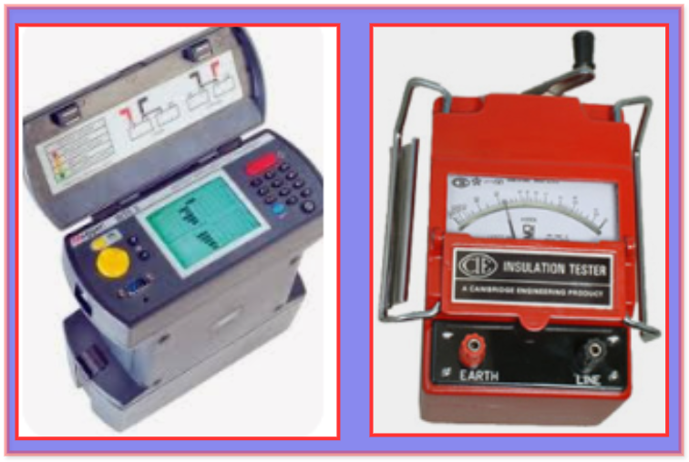
What is Megger?
A Megger is a portable electrical test instrument used to measure the insulation resistance of wires, cables, electrical components and equipment, and circuits. The megger generates a high voltage, ranging from 250V to 1000V or more, and measures the insulation resistance in megohms (MΩ).
A megger applies a high DC voltage across the insulation and measures the resulting leakage current. From this, it calculates the insulation resistance using Ohm’s law (Resistance = Voltage / Current). The measured resistance is compared to industry standards, historical data, or minimum acceptable resistance values to evaluate whether the insulation meets safety and performance requirements.
The analog scale of a megger displays the measured insulation resistance using a needle on a graduated scale. The scale is marked in megohms (MΩ) or gigohms (GΩ). The analog scale provides a continuous reading, and the user can observe fluctuations in resistance during the test. The Megger scale has zero (0) at one end and infinity (∞) at the other.
If the insulation resistance is high, the moving coil pointer will deflect toward infinity (∞). However, if the insulation resistance is low, the pointer will indicate close to zero resistance.
What is Megger test?
The Megger test uses an insulation resistance tester to assess the condition of electrical insulation in cables, wires, motors, transformers, and other electrical components.
An electrical wire has two main components: a conductor and an insulator. The inner metal core of the wire is the conductor, while the outer rubber coating on the conductor is the insulation. Users can safely touch the live wire due to the insulation covering, not the metal core. However, it is recommended to wear rubber gloves when handling live-insulated conductors.
Insulation is a type of resistance measurement. The higher the resistance, the better the insulation.
Insulation means the ability of the materials to resist the flow of electrical current, which is measured in terms of resistance. A higher resistance prevents current flowing through the material and indicates better insulation quality.
The quality of an electrical system’s insulation resistance declines with time and environmental conditions such as
The quality of an electrical system’s insulation resistance degrades over time due to various factors, including
- Aging
- Humidity
- Temperature
- Dirt and Oil
- Chemical Exposure
- Mechanical Stress
- Electrical stress
Apart from the above, electrical transients and surges can also impact insulation resistance(IR). Therefore, it is important to periodically measure and monitor insulation resistance to prevent potential electrical shocks or fatal accidents.
The IR measures an insulator’s ability to withstand a service voltage without a current leakage path. It indicates the state of an insulator.
The Insulation Resistance (IR) test measures a material’s ability to withstand a rated service voltage without allowing leakage current to pass through it. No leakage current at the rated service voltage indicates healthy and effective insulation.
It is tested with a Megger test. A Megger applies a DC voltage between its two probes and automatically calculates and displays the insulation resistance (IR) value.
Why is Megger Testing Performed?
The primary purpose of a Megger Test is to ensure the integrity of the wiring system. The insulation resistance test detects faults such as insulation breakdown, moisture intrusion, or aging, which could lead to electrical hazards or system failure. This test ensures the safety, reliability, and trouble-free operation of electrical installations.
During a fire or high-heat event (e.g., explosion), the wiring and its parts conductors and insulation are exposed to extreme temperatures. All metals and physical substances have specific melting threshold points. These thresholds can exceed and melt the wire and insulation during intense fires and affect the wiring’s current-carrying integrity.
When this happens, the resistance area increases, and the electrical current attempts to flow through the melted area. The increased current generates heat, which can ignite another fire. A significant concern is that damaged wiring may go unnoticed, especially when hidden behind walls, making it difficult to detect without proper testing.
Megger testing is a non-destructive method, making it an excellent choice for testing electrical insulation for faults or abnormalities without the need to create holes in walls.
The testing instrument operates within a relatively moderate voltage range of 500 to 1,000 volts. Due to the low voltage, some insulation punctures may go undetected. It generally provides valuable information about leakage current where the insulation is affected due to,
- Excessive dirt or Moisture
- Moisture Content
- Insulation Degradation
- Winding Issues
What is done during the Megger testing?
It is essential to test the circuits to detect any melted damaged areas and connections that may have been affected by the fire.
After analyzing the data, specific circuits can be identified and replaced to ensure that there are no further issues with the damaged wiring.
How Does Megger Testing Work?
A multimeter is sometimes used as an insulation tester to check continuity. However, a special device called an insulation tester detects and measures leakage current in normal or overloaded conditions.
It is essential to measure electrical leakage current in wires accurately and obtain highly reliable results, because current flows through the equipment during testing.
Users test the electrical insulation of various equipment, such as motors, wires, generator windings, and general electrical installations.
This is a widely used test that has been performed for a long time. It does not pinpoint the exact location of an electrical fault, it indicates the amount of leakage current and the moisture level in the electrical equipment, winding, or system. This test is useful for identifying potential issues that could lead to insulation failure. Regular testing can detect early signs of degradation and prevent breakdowns.
The procedure for conducting an insulation resistance test or megger test of the transformer is as follows:
First, users will disconnect the transformer’s line and neutral terminals.
The first step is disconnecting the transformer’s line and neutral terminals to isolate it from the power supply. This ensures that no current flows through the transformer during the test.
Megger test leads are attached to the LV and HV bushing studs to measure the Insulation Resistance IR value between the LV and HV windings.
Megger test leads are connected to the LV (low voltage) and HV (high voltage) bushing studs to measure the insulation resistance (IR) value between the LV and HV windings. This step evaluates the quality of insulation and identifies any potential weaknesses or faults between the windings.
Megger test leads are attached to HV bushing studs and the transformer tank earth point in order to measure the Insulation Resistance IR value between the HV windings and the earth.
To measure the insulation resistance (IR) between the high-voltage (HV) windings and the earth, Megger test leads are connected to the HV bushing studs and the transformer tank’s earth point.
To measure the insulation resistance (IR) between the low-voltage (LV) windings and the earth, Megger test leads are connected to the LV bushing studs and the transformer tank’s earth point.
The empirical relationship below provides the recommended minimum value for insulation resistance (IR) in megaohms (MΩ). This value indicates the insulation strength and helps determine whether it has degraded over time.
The minimum insulation resistance value,
IRmin (in MΩ) = kV + 1
Where kV = rated service voltage (KV).
For example, an 11 KV transformer should have a minimum insulation resistance value of 12 MΩ.
Megger Test Working Principle
- In a hand-operated Megger test, the testing voltage is generated by rotating a crank, whereas an electronic tester produces the testing voltage using a battery as its power source.
- 500 volts direct current is recommended for testing equipment with a voltage range of up to 440 volts. This ensures accurate measurement of insulation resistance without exceeding the equipment’s voltage rating.
- High-voltage electrical systems are tested using voltages ranging from 1000 V to 5000 V to assess their insulation resistance value.
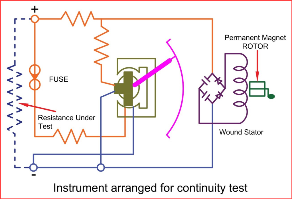
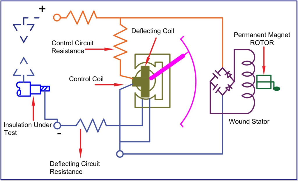
- The deflecting coil, also known as the current coil, is connected in series and allows the electric current drawn by the circuit to flow through it.
- The pressure coil, also called the control coil, is connected in parallel across the circuit.
- Current-limiting resistors (CCR and PCR) are connected in series with the control and deflection coils to protect them from damage in case of extremely low resistance in the external circuit.
- Hand-operated Megger tests utilize the principle of electromagnetic induction to generate the test voltage. This is achieved by arranging the armature to move within a permanent magnetic field or by moving the magnetic field around the armature.
- In contrast, an electronic type megger uses a built-in battery to generate the testing voltage. This allows for precise insulation resistance testing without relying on an external power source.
- As the voltage in the external circuit increases, the pointer deflection increases, while it decreases as the current increases.
- Therefore, the resulting torque is directly proportional to voltage and inversely proportional to current.
- When the electrical circuit being tested is open, the torque generated by the voltage coil reaches its maximum, and the pointer shows ‘infinity,’ indicating that there is no short circuit and maximum resistance within the circuit under test.
- If there is a short circuit, the pointer shows ‘zero,’ indicating that there is no resistance in the circuit being tested.
Megger Test for Cable- Step-by-Step Procedure
- Ensure the circuit is de-energized and disconnected from any power source to prevent electrical hazards.
- Isolate the cable from connected equipment to avoid damage during testing.
- Use a multimeter to confirm there is no residual voltage in the cable before starting.
- Select a tester with the appropriate voltage range for the cable (e.g., 500V, 1000V, or higher).
- Use insulated leads to connect the Megger to the cable.
- Wear gloves, safety glasses, and insulated footwear for protection.
- Use 500V DC for low-voltage cable..
- Use 1000–5000V DC based on the cable’s insulation rating for medium voltage cables.
- Follow manufacturer guidelines or standards like IEC or IEEE for correct voltage application.
- Attach one test lead to the conductor and the other to the cable insulation or sheath. For multi-core cables, test each core against the ground and between cores.
- Set the Megger to the desired test voltage. Apply the voltage steadily for a specific duration (typically 1 minute).
- Observe and record the insulation resistance value in megohms (MΩ).
- Evaluate the results against standard acceptable limits or manufacturer specifications.
- After the Megger test, connect the cable to the ground to eliminate residual electrical charge safely. If no faults are found, reconnect the cable to its circuit.
Important Points:
- Always adhere to safety protocols during the test.
- Do not exceed the recommended test voltage to prevent cable damage.
Advantages of Megger Testing
- Provides accurate insulation resistance measurements
- Detects potential faults or weaknesses in insulation
- Ensures the safety and reliability of electrical systems
- Detects leakage currents and moisture in equipment
- Prevents electrical failures and reduces maintenance costs
- Supports compliance with safety standards and regulations
- Easy to use and provides quick test results
- Ideal for both low and high-voltage systems
- Helps extend the lifespan of electrical equipment
Types of Megger Test
This can be divided into two main types:
- Electronic Type – Battery Operated
- Manual Type – Hand Operated
The following types of merger tests can be performed.
- Insulation Resistance Testing (IRT): Measures the insulation resistance between conductors or between conductors and the ground.
- Polarization Index (PI) Testing: Evaluates the insulation condition over a period of time by taking multiple resistance readings at different intervals of voltage application. PI is the ratio of the 10-minute IR value to the 1-minute IR value.
- DAR Testing: DAR is the ratio of 60 seconds IR value to 30 seconds IR value.
Advantages of the Electronic Type Megger Test
- A very high level of measurement accuracy
- Displays IR value in a clear, digital format for easy understanding.
- No need to rotate the crank as a manual Megger, one person can operate it easily.
- Delivers fast test results
- Its lightweight and compact design makes it easy to carry and use in various locations
- Data Storage and Transfer-Electronic Meggers come with data storage and connectivity features
- Reduced Maintenance
Advantages of the Hand-Operated Megger Test
- Due to the fact that it is one of the oldest methods for determining an IR value, still it maintains its significance in today’s highly technological environment. Although it is one of the oldest methods for determining an IR value, it still has significance in today’s highly advanced technological world.
- Hands-on control during testing
- Cheaper than electronic models
- No external power source is required, making them ideal for on-the-spot testing.
- Requires minimal maintenance and fewer components
- Built to withstand rough handling and tough working environments
Precautions for Megger Testing
The merger is a high-voltage equipment and safety precautions must be followed during merger testing. Failing to follow safety guidelines can harm you and your equipment.
- Always wear rubber gloves, safety goggles, and insulated footwear to protect against electric shocks and potential hazards.
- Use the Megger for high-resistance measurements, such as insulation testing or evaluating two separate conductors on a cable.
- Always adhere to the manufacturer’s instructions and guidelines for proper use and handling of the Megger.
- Before connecting a Megger test, ensure the circuit is completely de-energized and fully discharged.
- Before using a Megger test, disconnect the device being tested from other circuitry.
- Never touch the test leads while operating the handle.
- During the merger test, keep a safe distance from live electrical circuits
Megger Testing
Megger testing is a method used to measure the insulating resistance of electrical systems and equipment. It detects faults, degradation, or moisture that may affect insulation, ensuring safety and preventing malfunctions in electrical systems.
Related Articles: